


Valve Camshaft
23
Rev D
Figure 13
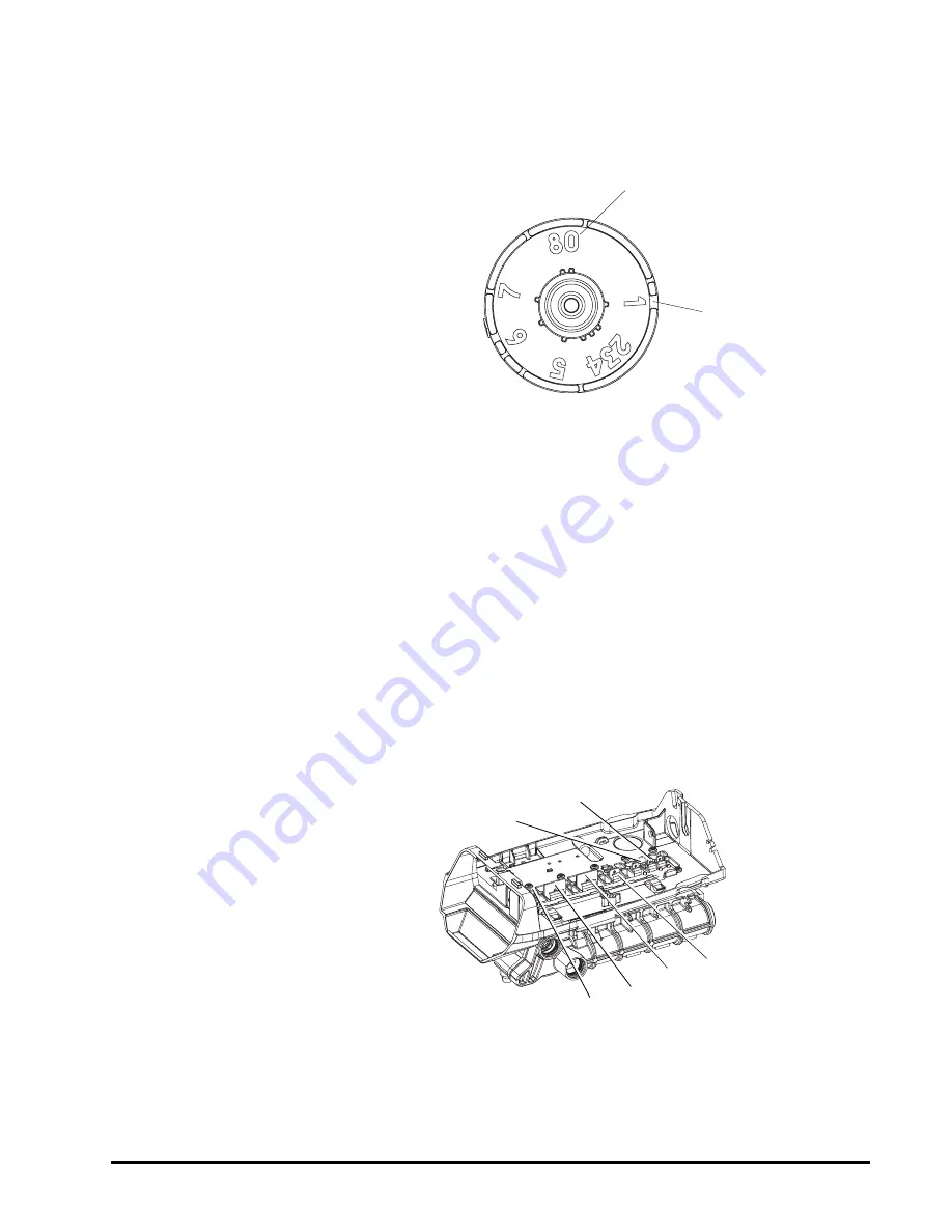
Camshaft Front End for 255, 263, and 268 valve bodies
The corresponding slot for the number is positioned at the optical sensor
which is approximately 90 degrees out of phase.
Regeneration Cycle Indicators
C0 = Treated Water - normal operation mode
C1 = Backwash Cycle
C2 = Regenerant Draw Cycle (not used in filter mode)
C3 = Slow Rinse Cycle (not used in filter mode)
C4 = System Pause (Repressurization cycle)
C5 = Fast Rinse Cycle 1
C6 = Backwash Cycle 2 (not used in filter mode)
C7 = Fast Rinse Cycle 2 (not used in filter mode)
C8 = Regenerant Refill (not used in filter mode)
Valve Disc Operation
Figure 14 - 255 Valve
Treated Water Slot
Treated Water Indicator
(normal operation)
1 Regenerant
2 Inlet
4 Bypass
3 Outlet
5 Rinse Drain
6 Backwash/Drain


