


Page 4
INSTALLATION MANUAL
REMOTE VEHICLE STARTER
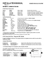
Yellow
Starter
30amp output
12volts during crank only.
Green
Heater
30amp output
12volts in accessory off during start.
Red
12 power
30amp input
Constant 12volt power at ignition harness.
Red
12 power
30amp input
Constant 12volt power at ignition harness.
Blue
Ignition 1
30amp output
12volts in ignition and start positions.
White
Select Output
30amp output
Selectable Output. See jumper diagram.
Yellow
Re-Arm 0.75sec Pulse On Shutdown.
(500ma Output)
Red/White
N/A Not Used on this model.
Brown
Disarm 0.75sec Pulse With Unlock And Before Start.
(500ma Output)
Orange
(-) Output (-) While Running
White/Blue
Horn (-) Horn Honk Output
Black/White
N/A Not Used on this model.
Purple
(+) Start Connect to positive start input.
White
Park Lights Positive Park light Output -
10 Amp Max.
Green/White
Hood Pin Negative Hood Pin Input -
MUST BE CONNECTED!!
Green
(-) Start Connect to negative start input.
Black
Ground System Ground Input -
MUST BE CONNECTED!!
Pink
Brake Positive Brake Input -
MUST BE CONNECTED!!
Blue/White
Tach
Tach Signal Input
-
Must be connected for Tach Mode!!
Blue
Glow Plug Programmable Input -
DIESEL ONLY.
Note:
500ma outputs are low current and are designed to activate relays.
* Connect only one start input. The start input will require 3 negative pulses within 2 seconds
To activate the remote starter.
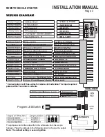
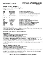
6 Pin Power Connector
14 Pin Connector
4 Pin Connector Blue - Program LED/ Switch
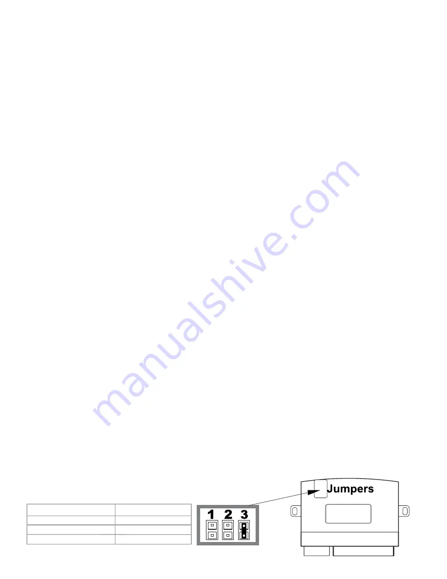
Jumper Selections
Program LED/Switch connector. The program switch is integrated into the LED. Press the LED to
activate the switch.
Position One
Second Starter
Output On the White Wire From The 6-Pin Connector.
Position Two
Second Accessory
Output On The White Wire From The 6-Pin Connector.
*Position Three
Second Ignition
Output On The White Wire From The 6-Pin Connector.
* The Default Setting For The System Is Second Ignition Output.
The jumpers control the output from the white wire at the 6-pin harness. Place the jumper in the following
positions to change the output.
Note: The default jumper setting is second ignition.
Output on White wire
Jumper position
Second Starter
Position 1
Second Accessory
Position 2
Second Ignition
Position 3
WIRING CONNECTIONS


