
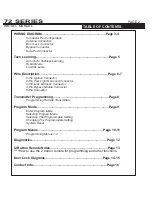

DOOR LOCK DIAGRAMS
Green
Vehicle's Lock/Unlock Switch
To Control
Relay or
Actuators
NEGATIVE DOOR LOCK
(LOW CURRENT)
Alarm and / or Starter
Module
Door lock Output
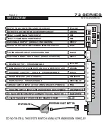
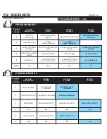
SYSTEM PROGRAMMING -
Menu 1
PAGE 14
INSTALL MANUAL
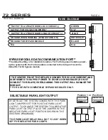
RELAY DIAGRAMS
Vehicle's Lock/
Unlock Switch
USE SPDT 12v Relay
Blue
NEGATIVE DOOR LOCK
(LOW CURRENT)
Ground
Ground
12volts
12volts
87
86
85
87a
30
87
86
85
87a
30
Alarm and / or Starter
Module
Door lock Output
Blue
Green
Vehicle's Lock/
Unlock Switch
USE SPDT 12v Relay
POSITIVE DOOR LOCK
(LOW CURRENT)
12volts
12volts
87
86
85
87a
30
87
86
85
87a
30
Alarm and / or Starter
Module
Door lock Output
Blue
Green
POSITIVE TYPE USING
INVERTER
Alarm and / or Starter
Module
Door lock Output
Blue
Green
VP-1
INVERTER
Vehicle's Lock/ Unlock Switch
Blue
Green
72 SERIES
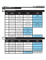
SYSTEM PROGRAMMING -
Menu 1
PAGE 15
INSTALL MANUAL
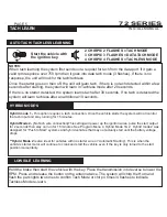
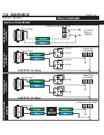
RELAY DIAGRAMS
Vehicle's Lock/
Unlock Switch
USE SPDT 12v Relay
NEGATIVE ONE WIRE
DOOR LOCKS
Ground
Ground
12volts
12volts
87
86
85
87a
30
87
86
85
87a
30
Alarm and / or Starter
Module
Door lock Output
Blue
Green
Unlock Resistor
Lock Resistor
Lock/ Unlock Switch
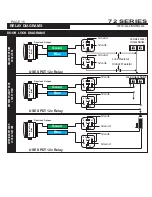
USE SPDT 12v Relay
REVERSE POLARITY DOOR
LOCK SYSTEM
12volts
12volts
Alarm and / or Starter
Module
Door lock Output
Blue
Green
87
86
85
87a
30
87
86
85
87a
30
x
x
x
x
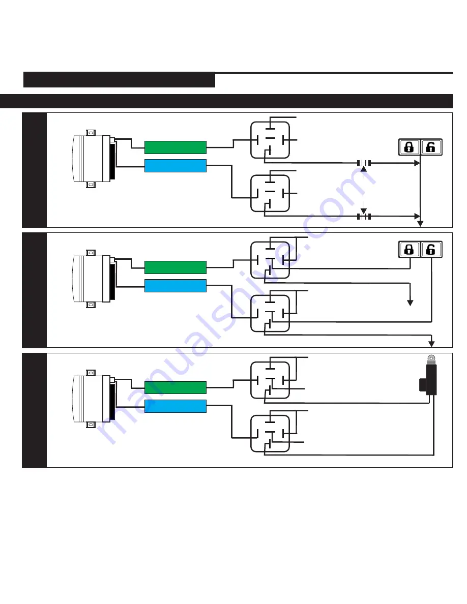
USE SPDT 12v Relay
AFTER-MARKET DOOR
LOCK ACTUATORS
12volts
12volts
Alarm and / or Starter
Module
Door lock Output
Blue
Green
87
86
85
87a
30
87
86
85
87a
30
Ground
Ground
DOOR LOCK DIAGRAMS
72 SERIES


