
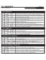
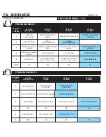


PIN 1
YELLOW
PIN 2
BROWN
PIN 3
BLACK
PIN 4
PIN 7
RED /WHITE
GRN/WHITE
PIN 5
PIN 8
WHITE/BLUE
BLUE/WHITE
PIN 6
PIN 9
PINK
BLUE
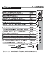
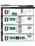
RE-ARM (-)
PROGRAMMABLE
Supplies one .75 second pulse when locked and one .75 second pulse
after remote start shutdown. Factory alarm re-arm/ RAP shutdown.
DISARM (-)
Supplies one .75 second pulse when the unlock button is pressed and
one .75 second pulse before remote start activation. For factory alarm dis-
arm/ or as computer “wake up”.
AUX #1
OUTPUT (-)
PROGRAMMABLE
Default- AUX channel output when the # button is held(no car finder on #)
Programmable for a (-) Ignition or (-) Dome Light output with the (#)
button activating car finder mode.
TRUNK
RELEASE (-)
HOOD PIN
INPUT (-)
Output activates when the unlock button is held for at least 3 seconds.
The output will stay on for up to 5 seconds if the button is held.
Programmable for Dome light Output or 2nd Unlock Output.
Connect
this wire to the supplied hood pin switch. If ground is detected on
this input the remote starter will not activate. Programmable for N/C hood
pin type (Factory hood pin)
HORN
OUTPUT (-)
PROGRAMMABLE
TACH WIRE
INPUT (A/C)
Connect this wire to the factory horn wire of the vehicle. This connection
will provide audible confirmation when programming and when a function
is performed.
This wire is
used to
to detect when the vehicle has started. The Tach
source is typically taken from a fuel injector, coil, coil pack or crank
position sensor. The Tach wire is generally found as the opposite from the
common wire at the coil or fuel injector.
BRAKE
SWITCH
INPUT (+)
GLOW PLUG
INPUT (+)
This wire must be connected to the wire at the brake switch that changes
to 12volts when the brake is pressed.
Default Gas Mode/ Positive Glow Plug. Programmable.
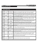
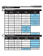
PIN 1
PIN 1
YELLOW
BLACK
PIN 2
PIN 2
GREEN
WHITE
PIN 3
RED
PIN 4
RED
PIN 6
BLUE
PIN 5
WHITE
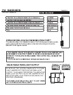
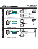
STARTER
OUTPUT
SYSTEM
GROUND
This wire will test 0V with the key off, in the Accessory position and when the
Ignition is in the on. This wire is 12volts in the start/ crank position only.
Connect to chassis ground.
HEATER
OUTPUT
PARK LIGHT
OUTPUT
(SELECTABLE)
This wire will test 0V when key is off, 12volts in the ACC and IGN positions
and off during the start/ crank position
Connect to the vehicles positive park light wire or change the jumper and
connect to the vehicle negative park light wire. The default position of the
jumper is
Positive Park Light Output.
12v INPUT 30A
Connect to constant 12volts. This input supplies the 12volt power for the
IGN 1, IGN 2 and Park Light output.
12v INPUT 30A
Connect to constant 12volts. This input supplies the 12volt power for the
Accessory and Starter output.
IGNITION
OUTPUT
This wire will test 0V in the off and Accessory positions then switch to12volts
in the Ignition and Start and run position.
SELECTABLE
OUTPUT
2nd Ignition, Accessory or Start output. Programmable.
Note: This output does not switch to default when the system is reset.
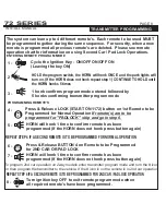
PIN 1
GREEN
PIN 2
N / A
PIN 3
BLUE
(-) LOCK
OUTPUT
Connect to lock wire from the switch on vehicles with a negative type switch.
**LOW CURRENT ONLY**
12V + DOOR
LOCK INVERTER
This output will supply 12volts for a plug-in type door lock module. Do not
use this input to power-up relays **LOW CURRENT ONLY**
(-) UNLOCK
OUTPUT
Connect to unlock wire from the switch on vehicles with a negative type
switch. **LOW CURRENT ONLY**
6-PIN CONNECTOR
9-PIN CONNECTOR
2-PIN CONNECTOR
3 PIN DOOR LOCK CONNECTOR
SYSTEM PROGRAMMING -
Menu 1
PAGE 6
INSTALL MANUAL
WIRE DESCRIPTION
72 SERIES
SYSTEM PROGRAMMING -
Menu 1
PAGE 7
INSTALL MANUAL
WIRE DESCRIPTION
72 SERIES
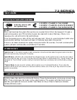
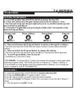
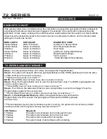
PIN 1
WHITE/
VIOLET
PIN 2
BLACK
PIN 3
RED
GROUND WHEN
RUNNING
This wire is used for bypass module activation or adding additional relays to
be triggered only when the remote starter activates.
GROUND
This wire can be used to supply ground to your bypass module.
12 VOLT OUT
This wire can be used to supply 12 volts to your bypass module. May not be
available on all harnesses. **LOW CURRENT ONLY**
3 PIN BYPASS MODULE CONNECTOR


