


Page 15
REMOTE VEHICLE STARTER
INSTALLATION MANUAL
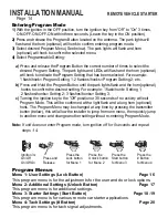
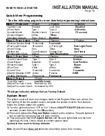
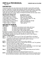
System Reset
Quick View Programming
* See the following pages for more detailed programming instructions.
Menu 1 -Press Lock
1 Flash
2 Flashes
3 Flashes
1 Ignition Lock
Enabled
Lock Only
Disabled
2 Horn Honk
Type 1
Type 2
All Honks
3 Lock&Unlock
Double Unlock
3 second
.75 second
4 Unlock/Disarm
125ms
750ms
5 Auxiliary Outputs
Type 1Type 2
Disabled
Menu 2 -Press Unlock
1 Flash
2 Flashes
3 Flashes
1 Secure Service Mode 15 seconds
5 seconds
2 Park Light Output
30 second
(-) Park Light
Park Light Flash
3 Horn Timing
5ms
50ms
10ms
4 Button #4
Trunk Release
Garage Door
Car Finder
5 Reservation Mode
Manual
Auto Reservation
Menu 3 -Press Start
1 Flash
2 Flashes
3 Flashes
1 Lock/ Unlock Type
Type 1
Type 2
Normal
2 Gas/ Diesel
Negative
15 second
Gas/ Positive
3 Rearm Output
Type 1
Type 2
Rearm
4 Run Time
4 Min
45 Min
15 Min
5 Crank Time
10 second
3 seconds
5 seconds
6 Starter Disable/ GWR Active
Passive
GWR
7 Safety Start Mode
Press twice
Press once
Menu 4 -Press #
1 Flash
1 Low Idle Learn
Low Idle Learn
2 Adjust For Over Crank
Reduced by 10%
3 Adjust For under Crank
Increased by 10%
**Bold type indicates settings that are Factory Default.
The system reset will clear any changes made to the Program Menu’s as well as the
Tach setting. When the system reset is complete the system must be Tach learned
before the remote starter will operate.
1)
Turn the ignition key from “Off” to “On” 3 times,
ON-OFF-ON-OFF-ON
within three
seconds
.
(Leave the key in the
ON
position)
2)
Press and release the
Program Button
located on the antenna. The park lights will
turn on and the horn (optional) will honk one time.
3)
Then press and hold the
Program Button
until the park lights flash and the horn
(optional) will honk 3 times slowly to confirm system reset.
System is now reset to factory defaults
.
Note:
System Reset
does not
delete the transmitter codes from memory.


