background image

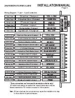
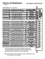
6 Pin Power Connector

6-pin

Description

Test For Wire

1-Yellow

30amp Starter Output

-

This wire will test 0volts in off, accessory and in

the ignition position.12volts during start only.

2-Green

30amp Heat/Acc Output

-

This wire will test 0volts in the off position 12-

14volts in the accessory and run positions and 0 volts during start

3-Red

30amp Power Input

-

12volts at ignition harness or from battery. Supplies

power for the ignition, selectable output and park light relays.

4-Red

30amp Power Input

-

12volt power at ignition harness or from battery.

Supplies power for accessory and start relays

5-Blue

30amp Ignition Output -

This wire will test 0volts in the off and accessory

position 12volts in the ignition, start and run

.

6-White

30amp Select Output -

Selectable output for 2nd Ign, acc or starter.

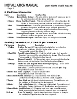
Auxiliary Connectors - 4, 11 and 14 pin Connectors

Pin Number

Function

Description

1-Yellow

Re-Arm Output

-

0.75 second pulsed output when locked and on

remote start shutdown. Used for factory alarm re-arm

.

Programmable output. See Menu 3

2-Red/Wht

Trunk Release Output (-) -

Hold the unlock button for 3 seconds.

Output will stay on until the unlock button is released (Max 5 seconds)
Programmable to (-)Park lights. See Menu 2

3-Brown

Disarm Output (-)

-

0.75sec pulsed output when unlocked and pulse

before remote start activation. Used for Factory Alarm Disarm.

4-Orange

Starter Kill and Negative While Running Outpu

t (-) -

Active when

armed and/or during remote start.

Anti-Grind -

Used for optional starter disable, and anti-grind relay

.

Programmable output. See Menu 3

5-White/ Blue Siren Output (+)

-

Output to activate siren.

Programmable output See Menu 1&2

6-Black/White Park Brake Input (-) -

Input to detect Park Brake Switch.

Connect switch that provides (-) when the switch is applied.

7-Purple

Door Pin Input (+)

-

Input to detect open door. Connect to door pin

that switches to 12volts when the door opened.

8-White

Park Lights Output (+) -

+10amp park light output. Connect to circuit

0volts when Parking Lights are off, 12volts when park lights are on.

9-Green/White Hood Pin Input (-) -

Negative input from hood pin safety switch.

Switch is grounded when the hood is opened. Must be connected.

10-Green

Door Pin Input (-) -

Input to detect open door. Connect to door pin

that switches to Negative when the door is opened.

Page 8

INSTALLATION MANUAL

2WAY REMOTE STARTER/ALARM

Summary of Contents for 42 SERIES

Page 1: ...vehicle owner to ensure that this is done The manufacturer accepts no liability or responsibility for accidental starting of the vehicle CARBON MONOXIDE Never Start in an Enclosed Building Garage Carp...

Page 2: ...s Important Tach Notes Page 12 13 Auto Tach Learn Quick Tach Learn Program Overview and Quick View Programming Page 14 15 Entering Program Mode Quick View Programming System Reset Programming Menus Pa...

Page 3: ...e proper tools and testing equipment is also very important Never use a grounding style test light to test for wires in the vehicle Use only a Circuit Safe test light or digital Volt Ohm Meter It is t...

Page 4: ...s such as brake clutch and gas pedal linkages Do not place the module directly in front of a heater vent Installing the External Long Range Antenna To insure the best possible reception place the ante...

Page 5: ...4 5 6 7 8 9 10 11 15 12 13 14 WHITE Factory Re arm Output Starter kill Anti Grind Output Factory Disarm Output Trunk Release Output Siren Output 10amp Park Light Output Negative Door Pin Input Negati...

Page 6: ...Diesel Glow Plug Input BLUE WHITE YELLOW WHITE BLUE BLACK BROWN RED WHITE PINK BLUE WHITE GREEN WHITE 250ma Output ORANGE 250ma Output 250ma Output 250ma Output Positive Output or Input Negative Inpu...

Page 7: ...e jumper is in position 3 the output on the white wire will be 2nd Ignition The factory default setting of the selectable output jumper is position 3 Output on White wire Jumper position Second Starte...

Page 8: ...Output Hold the unlock button for 3 seconds Output will stay on until the unlock button is released Max 5 seconds Programmable to Park lights See Menu 2 3 Brown Disarm Output 0 75sec pulsed output wh...

Page 9: ...ogrammable Menu 1 Setting 3 The centre pin of the keyless entry harness is not to be used for anything besides plug in devices such as the VP 1 DL 3 DL 7 and Data Bus Modules Overloading this output w...

Page 10: ...ts AC Pink Brake Switch Connect To When Brakes Is Applied White Blue Siren Output Connect to Siren Horn Manual Transmission Connections M Models Only Black Wht Park Brake Input Connect to Park Brake w...

Page 11: ...ry bypass the clutch switch should never be disconnected or altered to not work as it is indented to As a Safety Switch The clutch switch is usually a 2 wire switch mounted directly to the clutch peda...

Page 12: ...ts do not flash in auto tach learn mode it may be necessary to connect to a different tach source It is important the ignition output from the remote starter is connected to a wire that does not turn...

Page 13: ...al idle RPM Vehicles such as Toyota and Honda will run at a very high idle for a number of minutes when first started If tach learned when the vehicle is at high Idle then remote started when the vehi...

Page 14: ...ng 3 c Turning the ignition key to the Off position or 30 seconds of no activity will exit Program Mode This will be confirmed with a light flash and a long siren chirp The Program Menu may be changed...

Page 15: ...ank Time 10 seconds 3 seconds 5 seconds 6 Starter Disable GWR Active Passive GWR 7 Safety Start Mode Press twice Press once Menu 4 Press 1 Flash 2 Flashes 3 Flashes 1 Low Idle Learn Low Idle Learn 2 A...

Page 16: ...75 Sec Lock Unlock 3 Flashes Chirps 75 Second Lock Unlock Pulses Press Release the Program Button 3 Times Setting 3 Confirmed with 3 LED flashes Press Hold the Program Button until the appropriate of...

Page 17: ...flashes Press Hold the Program Button until the appropriate of park light sirenchirps then release Press Release the Program Button to proceed to the next step Setting 2 Parking Light Trunk Output 14...

Page 18: ...n the board layout 11 or 14 pin connectors Default Settings Setting 4 Button 4 Programmable 1 Trunk Release 1 Flash chirp Holding button 4 will activate Trunk Release 2 Garage Door 2 Flashes chirps Ac...

Page 19: ...flashes Press Hold the Program Button until the appropriate of park lights siren chirps then release Press Release the Program Button to proceed to the next step Setting 5 Maximum Crank Time 1 10 Sec...

Page 20: ...Button The park lights flash and the siren will chirp one time Each time the park lights flash and the siren chirps the setting is reduced 5 Release the Program Button Exit Program Mode and test remo...

Page 21: ...not pause more than one second between each transmitter All the transmitters to be used must be programmed at the same time All transmitters not programmed at this time will be erased from memory for...

Page 22: ...Door Locks More Than 250ma Positive Type Door Locks Note When installing relays always use a fused power source Blue Green Lock Un lock Vehicle Lock Unlock Switch To Control Relay or Actuators 87 86 8...

Page 23: ...30 Ground DIAGNOSTICS 13 87 86 85 87a 30 87 86 85 87a 30 Blue Green Lock Un lock To Vacuum Pump Fused 12V x Cut Ground Page 23 2WAY REMOTE STARTER ALARM INSTALLATION MANUAL 5 Wire Reverse Polarity Ty...

Page 24: ...start attempts without starting Being that the installer does not always see when the system shuts down or fails to start Diagnostic Memory will store in memory up to four shutdown codes This informa...

Reviews: