
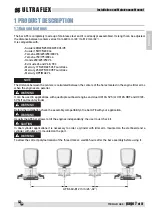

TIE BAR A98
-
page 9
of 51
Installation and Maintenance Manual
ENGLISH
ULTRAFLEX
2 INSTALLATION
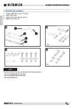
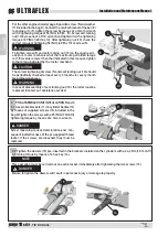
2.1 Necessary tools
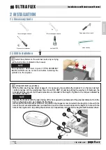
2.2 A98 Installation
22 mm hexagon wrench
Dynamometric wrench
Cross slot screwdriver
Loctite® 270
2x
4mm hex key
14 mm hexagon wrench
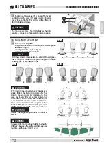
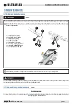
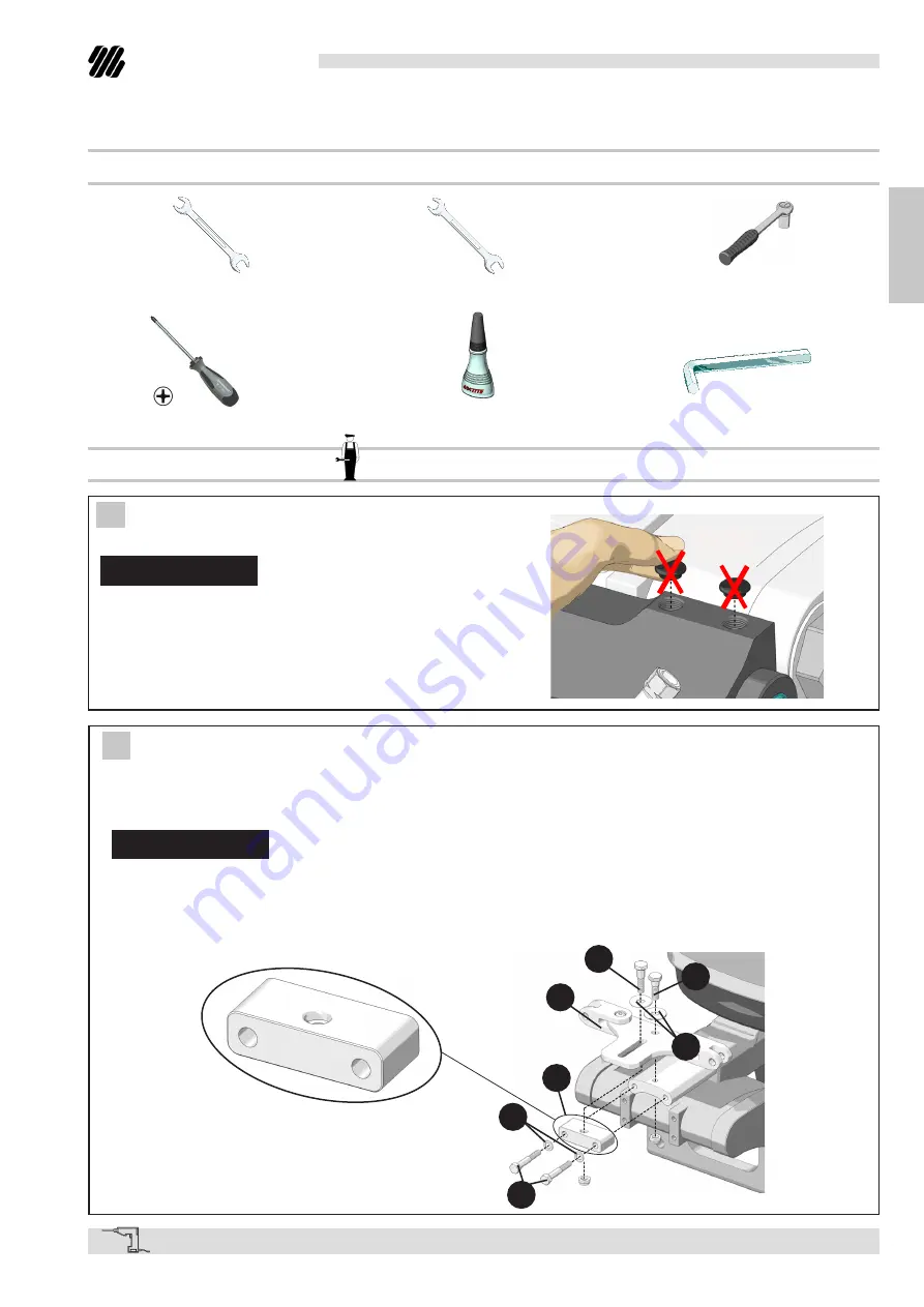
2 BRACKET INSTALLATION A
With the Mercury Engines listed at page 8, it is necessary to assemble the bracket (1) on the two internal/
central engines arm by positioning the screws 5/16 UNF (2) and by putting the washers (3) between the
bracket and the screws. (All these elements are included in the bag E). Tighten to the torque indicated by
the motor mechanic.
NOTE
Position the bracket with the spot-facing of the hole upwards and placed at the greatest distance from the
hole on the engine arm, as indicated in the figure.
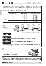
Assemble the central bracket of the bar (A), position the longest screw included in the bag E (4) in line with the
hole of the just assembled bracket, and position one of the two screws included in the bag D (5) in line with the
hole of the engine arm, by putting the washers (6) (respectively included in the bag D and E) between them.
5
4
A
6
1
3
2
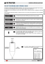
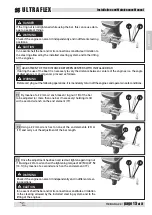
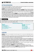
1 Install the cylinders on the external motors by carrying
out the instructions indicated in the manual.
NOTE
The operations described in point 3 PRE-ASSEMBLY
INSTALLATION can be carried out before installing the
cylinders on the engines.
Summary of Contents for A98
Page 16: ...Installation and Maintenance Manual ULTRAFLEX page 16 of 51 TIE BAR A98 ENGLISH NOTES...
Page 17: ...TIE BAR A98 page 17 of 51 Installation and Maintenance Manual ENGLISH ULTRAFLEX NOTES...
Page 19: ...BARRA D ACCOPPIAMENTO Manuale di installazione e manutenzione ULTRAFLEX R SOCIO A98...
Page 37: ...BARRE D ACCOUPLEMENT Manuel d installation et d entretien ULTRAFLEX R ASSOCIE A98...
Page 52: ...ULTRAFLEX S p A 16015 Casella Genova Italia Via Crose 2...


