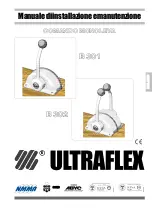
SINGLE LEVER CONTROL B301 AND B302
-
page 11
of 47
Installation and maintenance manual
ULTRAFLEX
E
N
G
L
ISH
7
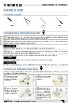
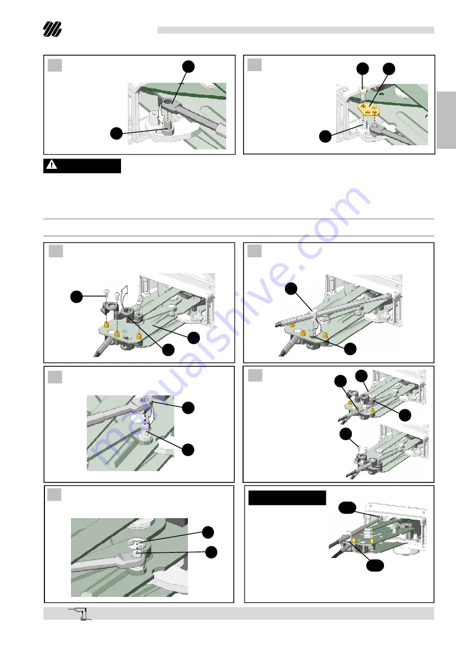
Engage the rod
(13) on the pin (I)
8
Mount the plate
(H) in the way shown
in the picture and fix
it with the screw (G)
on the hole (14).
Check the right setting of shift cable stroke and make sure that is compliant with the following conditions.
WARNING
During the shift engagement, the lever movement must be always fluid with a constant resistance.
The lever must no become stiffer during the throttle engagement, otherwise check that the control shift
stroke corresponds to the engine one.
13
I
G
H
14
3.5.2 Throttle cable connection
1
Remove the cable fastener (7) from the plate
(8) removing the screws (9).
3
Engage the rod (16) on the pin (17).
7
8
9
4
Remount the cable
fastener (7) on the plate
(8) aligning the cable
cylinder (10) with the
hole of the cable
fastener.
Fix the cable fastener
to the plate with the
screws (9).
2
Mount the cable making sure the cable
cylinder (10) is placed inside the plate hole (15).
15
10
10
7
8
9
16
17
5
Fix the cable inserting the circlip (E) in the
groove of the pin (17).
E
17
NOTICE
17A
15A
For push action
throttle, connect the
cable rod on the pin
(17A) and insert the
cable cylinder into
the plate hole (15A).


