background image

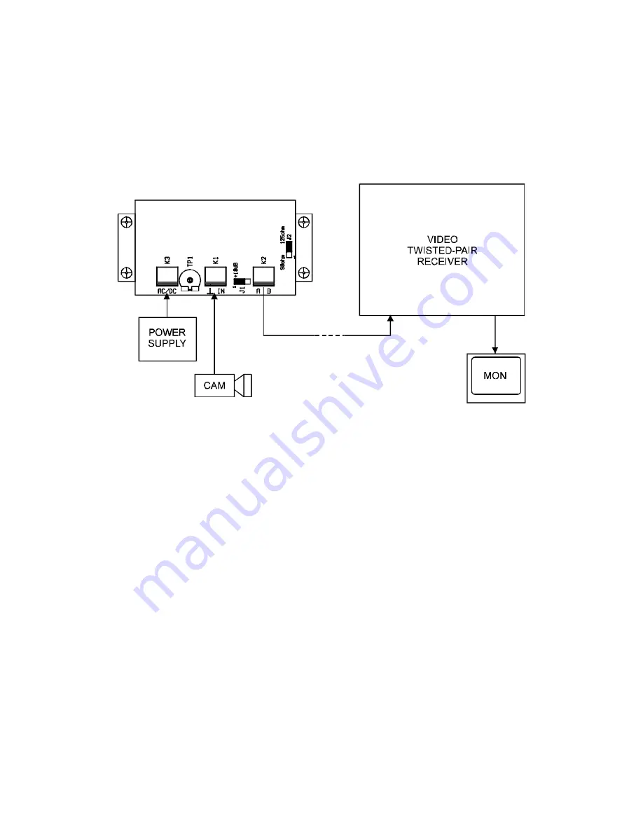
CONNECTIONS 


Be sure to switch-off the power supply unit 
before connecting to other equipment. 


Also refer to the instruction manual of the 
equipment to be connected. 


INSTALLATION 


(1)  Set the jumper 

J1

 to 0 dB. 

(2)  Set the jumper 

J2

 to correct position. (125 ohm for PE or PAPER, 90 ohm for PVC cable insulation) 

(3)  Connect the power supply unit (AC or DC) to the 

K3

(4)  Connect the video test generator (1 Vpp / 75 

) to the 

K1

(5)  Switch-on the power supply unit. 

(6)  Switch-on the video test generator. 

(7)  Check the positive video output signal between 

and 

(8)  Check the negative video output signal between 

and 

(9)  Switch-off the power supply unit. 

(10)  Switch-off the video test generator. 

(11)  Disconnect the video test generator. 

(12)  Connect the twisted-pair cable to the 

K2

(13)  Connect the video source (video camera) to the 

K1


Note: 


Do not adjust the trimmer 

TP1

.


Summary of Contents for VZ-20-T

Page 1: ...VZ 20 T VIDEO TWISTED PAIR TRANSMITTER Operating instructions Ultrak Italia Via Treviso 2 4 l 31020 San Vendemiano Treviso Italy 39 0438 3651 l FAX 39 0438 370471 ...

Page 2: ...2 ...

Page 3: ...RN WISSEN UND GEWISSEN ERSTELLT ULTRAK LEHNT JEDWEDE REGRESSANFORDERUNGEN FÜR EVENTUELLE ENSTEHENDE FOLGEN AUS DER NUTZUNG DIESER INFORMATION AB ÄNDERUNGEN VORBEHALTEN NEUE ODER ÜBERARBEITETE AUSGABEN KÖNNEN SOLCHE ÄNDERUNGEN BEINHALTEN TOUS DROITS RESERVES AUCUNE PARTIE DE CETTE PUBLICATION NE PEUT ETRE REPRODUITE PAR QUELQUE MOYEN QUE CE SOIT SANS ACCORD ECRIT DE ULTRAK LES INFORMATIONS SONT REP...

Page 4: ...NTS Preface 4 Features 4 Block diagram 4 Principle of operation 4 Controls and connectors 5 Connections 6 Installation 6 Appearance 7 Specifications 7 This unit is produced to comply with Directive 89 336 EEC ...

Page 5: ...e use of different kinds of cables FEATURES small dimensions simple connecting AC DC power supply low power consumption over voltage protection dual output impedance pre emphasis 10 dB 5 MHz BLOCK DIAGRAM PRINCIPLE OF OPERATION The input is closed with the impedance of 75 Ω The clamping is set with the trimmer TP1 Then follows the stage which defines the pre emphasis By means of the symmetry stage...

Page 6: ...6 ...

Page 7: ...UPPLY Power supply terminal block connector 2 TP1 Clamping adjustment trimmer 3 VIDEO INPUT Video input terminal block connector 4 J1 Pre emphasis jumper 5 TWISTED PAIR OUTPUT Twisted pair terminal block connector 6 J2 Output impedance jumper ...

Page 8: ... power supply unit AC or DC to the K3 4 Connect the video test generator 1 Vpp 75 Ω to the K1 5 Switch on the power supply unit 6 Switch on the video test generator 7 Check the positive video output signal between A and 8 Check the negative video output signal between B and 9 Switch off the power supply unit 10 Switch off the video test generator 11 Disconnect the video test generator 12 Connect t...

Page 9: ... Video output 2 x 2 Vpp Output impedance 125 Ω 90 Ω J2 Freq response 30 Hz 5 MHz 0 5 dB Pre emphasis 10 dB 5 MHz J1 Power supply 24 V AC DC 100 mA max Power supply protection varistor Casing ABS Dimensions 106 W x 55 5 H x 100 D mm Protection IP 65 VDE ...

Reviews: