2.2 Physical
Description
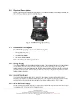
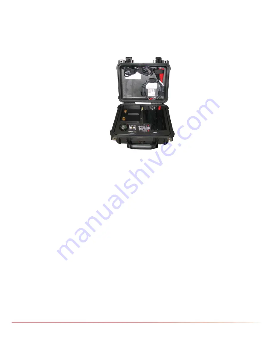
Figure 1 shows the physical layout of the charger. The CH0004 consists of two charge modules, an
AC to DC Power Module and a Control/Filter Board.
Figure 1: CH0004 Charger (Front View)
2.3 Functional
Description
The CH0004 Charger (Figure 1) consists of the following items:
Charge Module (2 ea.)
Control/Filter Board
AC to DC Power Supply
Each is described in the following subsections.
2.3.1 Charge Supply
The Charge Modules are non-repairable potted modules. These modules accept a DC input voltage,
monitor battery selection and provide the charging functions for the battery to be charged. The
battery detection circuit, discharge switches, battery charge indicator LEDS and charge circuitry are
all located on these boards. Each module provides the necessary voltage/current parameters to the
battery charge connectors.
2.3.2 Control/Filter Board
The Control/Filter Board accepts the AC and/or DC input power, contains self-resetting circuit
breakers to protect the unit, filters for EMI suppression, a 5V regulator for charger modules and fan,
and functions as the interconnect point between the charge modules and AC to DC Power.
2.3.3 AC to DC Power Supply
The AC to DC Power Module accepts a 115-230 VAC, 50/60 Hz AC input and converts the AC input
to a regulated 25V DC output to the Charge Modules.
CH0004 Operation Manual
Newark, New York | 315-332-7100 | Fax: 315-331-7800
©2010 Ultralife Corporation • www.ultralifecorp.com • All specific subject to change without notice
The information contained herein is for reference only and does not constitute a warrant of performance •
30 SEP 10 UBI-5157 Rev: E
Page 8 of 15


