SonixMDP/SP/OP Service Manual 00.053.205, Revision A
Chapter 6: Peripherals and Accessories
6-1
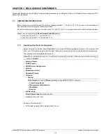
CHAPTER 6: PERIPHERALS AND ACCESSORIES
6.1
PERIPHERAL COMPONENTS
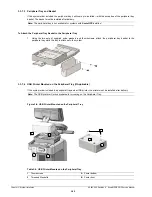
The 1-position AC peripheral receptacle is located on the back of the system (to the left of the EMI filter). The connector is
clearly labeled “
Only Ultrasonix-approved peripheral devices may be connected to this power receptacle
” and is to be
used to connect only Ultrasonix-approved, third-party peripherals to the system.
6.2
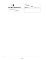
ULTRASONIX-APPROVED DEVICES
The following peripherals have been approved for use with the system:
• SONY USB printer (
)
• USB media (memory stick, external hard drive, etc.)
• dual or triple footswitch
• barcode reader (not available on SonixOP Q+)
• extra (DVI-compatible) LCD display (
).
6.3
PRINTER SETUP
6.3.1
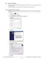
Local Printer Setup
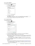
To Connect the USB Printer:
1.
Ensure the printer has been installed.
2.
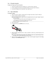
Connect the peripheral receptacle power cord to the printer and the peripheral receptacle (
3.
Insert the USB connector into one of the USB ports on the Back Connectivity Panel.
4.
Ensure the system in plugged in and powered on.
5.
The USB printer will automatically communicate with the system and configure itself.
6.
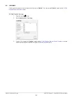
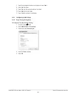
Configure
Custom Keys
(
) and
Image Sheet Printing
) as required.
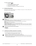
Caution:
Only Ultrasonix-approved peripheral devices (
) may be connected to the system’s peripheral receptacle (
).
Refer to the most recent price list to determine the exact make(s)/model(s) of Ultrasonix-approved devices.
Warning:
It is the Operator’s responsibility to ensure that any peripheral device placed within the patient environment* –
including printers and external displays – conforms to the following:
Accessory equipment connected to the analog and digital interfaces must be certified according to their respective IEC
standards (e.g., IEC 60950 for data processing equipment and IEC 60601–1 for medical equipment). Furthermore, all
configurations shall comply with the system standard IEC 60601–1. Any person who connects additional equipment to
the signal input part or signal output part configures a medical system and is therefore responsible for ensuring that the
system complies with the requirements of the system standard IEC 60601–1–1. If in doubt, consult Ultrasonix Technical
Support.
*The patient environment is defined as a 1.5 m (4.9’) radius from the edge of the patient platform (i.e., from the outer
edge of the chair/bed on which the patient is situated in order to perform the ultrasound).
Caution:
DO NOT plug the extra (HDMI-compatible) LCD display into the peripheral receptacle (
). Refer to
for instructions on connecting/installing the removable (peripheral) hardware.
Note:
The power cord supplied with the USB printer cannot be plugged into the system's peripheral
receptacle. USB printers supplied by Ultrasonix will come equipped with this extra power cord.
Note:
If these USB ports are already in use, rearrange the system's external USB connections, making use of
the additional USB ports located on the side of the console.
Summary of Contents for Sonix MDP
Page 1: ...Analogic Ultrasound Service Manual SonixMDP SP OPQ Ultrasound System...
Page 2: ......
Page 4: ......
Page 14: ...Chapter 2 System Specifications 00 053 205 Revision A SonixMDP SP OP Service Manual 2 2...
Page 46: ...Chapter 5 Software 00 053 205 Revision A SonixMDP SP OP Service Manual 5 4...
Page 120: ...Chapter 8 DICOM 00 053 205 Revision A SonixMDP SP OP Service Manual 8 24...
Page 147: ......

