Chapter 7: Field Service Components
00.053.205, Revision A SonixMDP/SP/OP Service Manual
7-20
5.
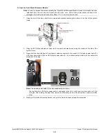
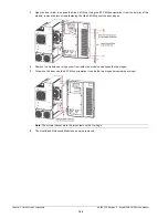
Using the 10mm wrench, fasten the washer and nut securing the ground mesh from the modulo to the console.
6.
Using the 7mm wrench, fasten the washer and nut securing the ground wire from the modulo to the LCD
display and, if applicable, to the ECG (refer to image
7.
Ensure all cables are properly connected to the System Case Connectivity Panel.
8.
Test the modulo and UPS to ensure the system powers up and runs correctly (
9.
Once the modulo and UPS test is successfully completed, use as many cable ties as necessary to neatly
fasten all cables, keeping them tucked out of the way.
10.
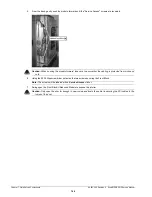
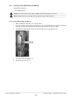
Reinstall both side shrouds (
7.3.3
Connectivity
Once the modulo has been replaced, all cables and wiring must be properly reconnected. Use the images and
descriptions in the following sections to ensure this is accomplished correctly.
7.3.3.1 System Case Connectivity Panels
The System Case Connectivity Panel (SCCP) is accessible only after removing the side panel (
). Check to
ensure that all cables are securely plugged into their respective slots.
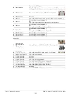
Figure 7-4: PHW4MOD1.0
Note:
to ensure the proper connections are made.
Note:
If the system was ordered without a UPS, test the modulo following the instructions in
8
7
31
10
17
33
20
26
25
12b
12a
19
21
34
36
3
38
40
35
39
37
28
14
42
11
43
44
C
G
D
E
H
K
F
I
J
Power Hub
Summary of Contents for Sonix MDP
Page 1: ...Analogic Ultrasound Service Manual SonixMDP SP OPQ Ultrasound System...
Page 2: ......
Page 4: ......
Page 14: ...Chapter 2 System Specifications 00 053 205 Revision A SonixMDP SP OP Service Manual 2 2...
Page 46: ...Chapter 5 Software 00 053 205 Revision A SonixMDP SP OP Service Manual 5 4...
Page 120: ...Chapter 8 DICOM 00 053 205 Revision A SonixMDP SP OP Service Manual 8 24...
Page 147: ......


