Compressor Unit Instruction Manual
ULVAC CRYOGENICS INCORPORATED
3-7
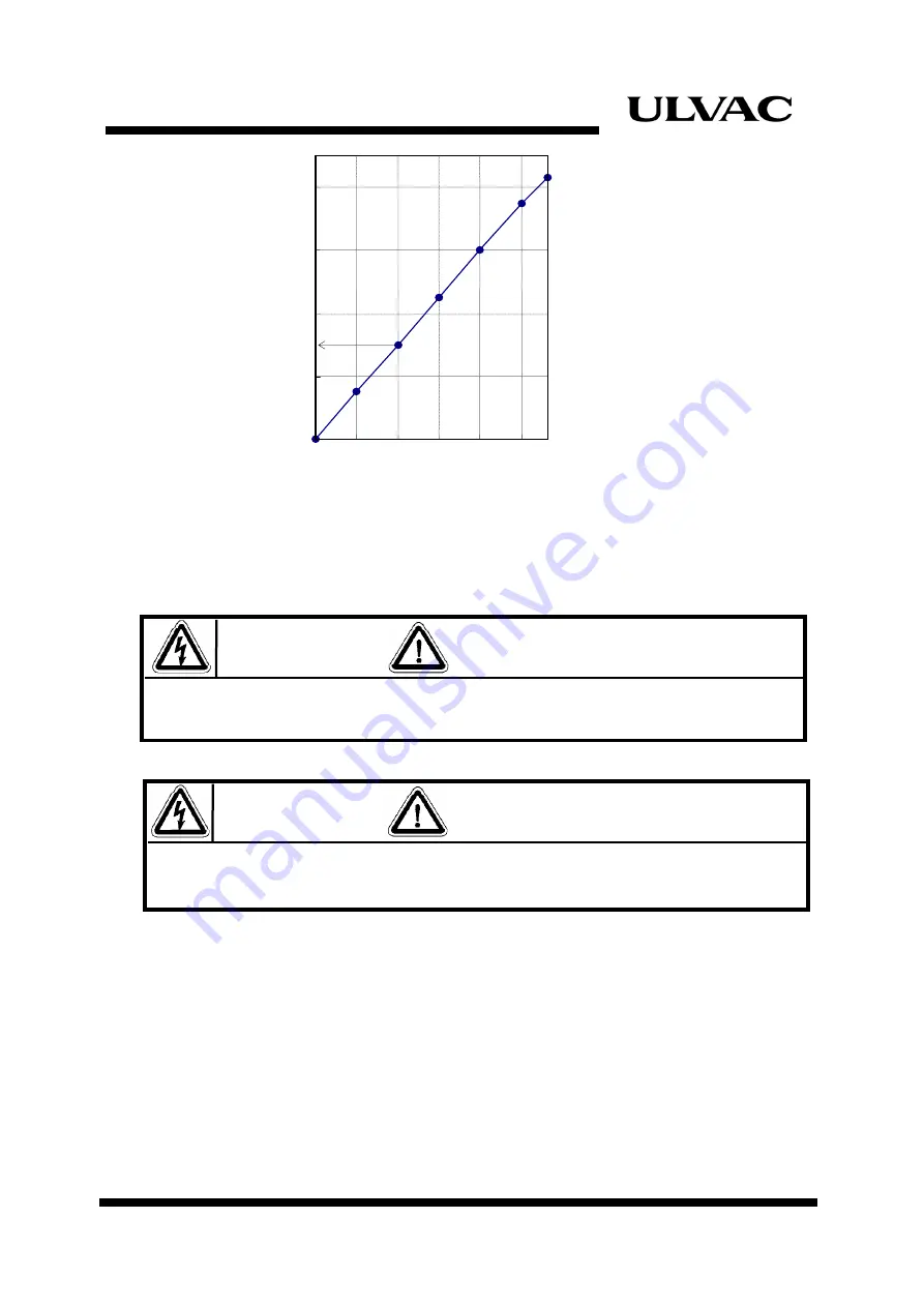
Figure 3-4
Static Pressure and Temperature
3.5 Connecting Electrical Cables
Do not connect the compressor to power supply until all wiring and connections are
completed.
Disconnect the input power connector at REMOTE/RESPONSE wiring. Failure to observe
this precaution could result in damage to, or destruction of, the equipment.
◆
REMOTE WIRING
:Set the REMOTE/LOCAL switch to
「
REMOTE
」
position.
Make the REMOTE wiring according to the circuit diagram shown in
Appendix B. Always use the momentary switch (contact) for setting
START/STOP push button switch (PB1, PB2) in remote operation.
◆
RESPONSE WIRING
:Be sure to make wiring for RESPONSE signals. The relay
specification of response signals is shown in Appendix B.
1.67
1.71
1.75
1.79
1.83
10 15 20
25
30
35 38
Temperature °C
Cha
rge Pressure
MPaG
1.73
WARNING
WARNING
1.
Make the REMOTE/RESPONSE wiring, if necessary.
Summary of Contents for C10T
Page 2: ......
Page 8: ...F 6 ULVAC CRYOGENICS INCORPORATED This page intentionally left blank ...
Page 14: ...S 4 ULVAC CRYOGENICS INCORPORATED This page intentionally left blank ...
Page 16: ...IW 2 ULVAC CRYOGENICS INCORPORATED This page intentionally left blank ...
Page 32: ...Operation 4 2 ULVAC CRYOGENICS INCORPORATED This page intentionally left blank ...
Page 44: ...Troubleshooting A 4 ULVAC CRYOGENICS INCORPORATED This page intentionally left blank ...
Page 47: ...Compressor Unit Instruction Manual ULVAC CRYOGENICS INCORPORATED B 3 B 4 ...
Page 48: ...Compressor Unit Instruction Manual ULVAC CRYOGENICS INCORPORATED B 5 B 6 ...
Page 50: ...Flexible Hose C 2 ULVAC CRYOGENICS INCORPORATED This page intentionally left blank ...
Page 54: ...CS 2 ULVAC CRYOGENICS INCORPORATED This page intentionally left blank ...
Page 56: ...This page intentionally left blank R 2 ULVAC CRYOGENICS INCORPORATED ...


