Installation
3-2
ULVAC CRYOGENICS INCORPORATED
3.2
Connecting Cooling Water Piping
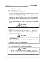
Install the cooling water piping as follows:
1.
Cooling water inlet/outlet connector: Rc3/8 female.
2. Water pipes should be made of materials with pressure resistance of larger than 1.5 times
of the cooling water inlet such as plastic or copper.
3.
It is recommended that a filter is installed in the water line between the cooling water
main valve and the compressor unit to prevent water scales. It is also recommended to
install a flow meter (approx.0 - 15L/min.) between the filter and the compressor unit to
check the flow rate.
4.
Ensure to connect inlet/outlet to the right place. Do not connect them the wrong way
around.
Check water connections for leaks.
3.3
Cooling Water
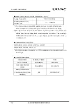
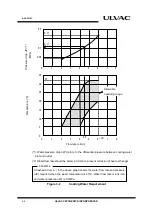
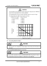
1. Determine the cooling water flow rate within the allowable range as shown in Fig. 3-2.
Always use the proper cooling water that meets the requirement. Keep the cooling water
supply pressure less than 0.7MPaG.
・
If the temperature of cooling water is below 5°C, it can cause overloading or a difficulty
in starting the compressor.
・
If the temperature of cooling water is higher than 32°C, the thermal switch will be
activated due to the overheat and turn off the compressor.
・
Excessive flow rate reduces the life of heat exchanger.
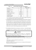
2. For the standard quality of cooling water, we refer to the water quality control standard set
by The Japan Refrigeration and Air Conditioning Industry Association.
・
Usage of poor quality water causes performance degradation of heat exchanger.
・
If the water quality does not satisfy the requirement, it shortens the lifetime of the
heat exchanger.
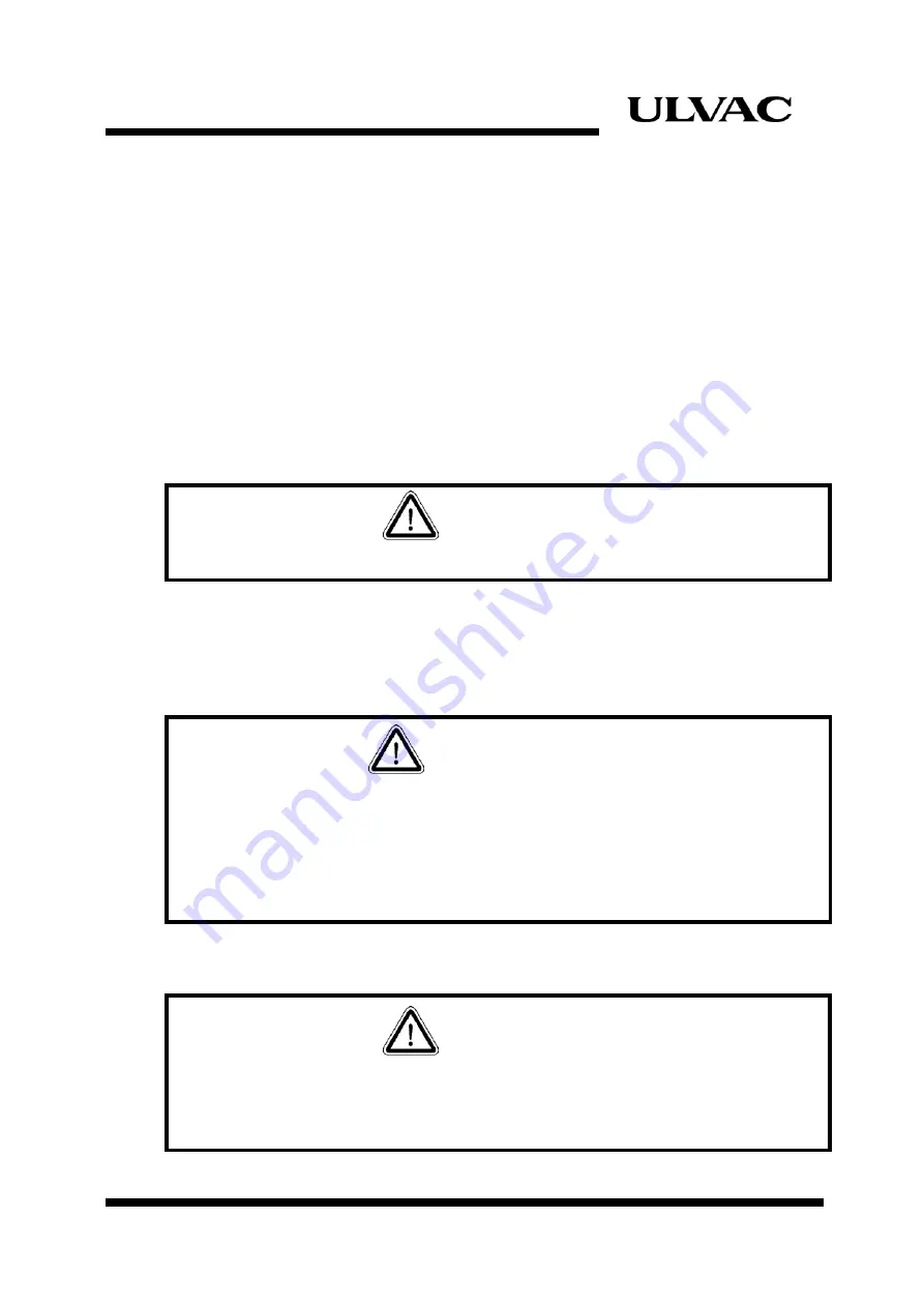
CAUTION
CAUTION
CAUTION
Summary of Contents for C15T
Page 2: ......
Page 8: ...F 6 ULVAC CRYOGENICS INCORPORATED This page intentionally left blank...
Page 14: ...S 4 ULVAC CRYOGENICS INCORPORATED This page intentionally left blank...
Page 16: ...IW 2 ULVAC CRYOGENICS INCORPORATED This page intentionally left blank...
Page 34: ...Operation 4 2 ULVAC CRYOGENICS INCORPORATED This page intentionally left blank...
Page 38: ...Disconnection and Storage 5 4 ULVAC CRYOGENICS INCORPORATED This page intentionally left blank...
Page 46: ...Maintenance 6 8 ULVAC CRYOGENICS INCORPORATED This page intentionally left blank...
Page 50: ...Troubleshooting A 4 ULVAC CRYOGENICS INCORPORATED This page intentionally left blank...
Page 54: ...Circuit Diagram B 4 ULVAC CRYOGENICS INCORPORATED This page intentionally left blank...
Page 57: ...Flexible Hose C 2 ULVAC CRYOGENICS INCORPORATED This page intentionally left blank...
Page 61: ...CS 2 ULVAC CRYOGENICS INCORPORATED This page intentionally left blank...
Page 63: ...Revisions R 2 ULVAC CRYOGENICS INCORPORATED This page intentionally left blank...


