Compressor Unit Instruction Manual
ULVAC CRYOGENICS INCORPORATED
3-5
3.4
Connecting the Compressor Unit to the Cryopump
・
Read the handling notes in appendix C about the connection of the flexible hoses.
・
When connecting flexible hoses, always use two single open end spanners with width
across flat 26mm and 30mm.
・
Do not forcibly bend flexible hoses. They may be damaged and cause helium leakage.
・
Do not connect or disconnect self-sealing coupling frequently. It may cause helium
leakage .
1
.
Remove all dust plugs and caps from the supply and return flexible hoses, compressor
and cryopump. Clean the self-sealing coupling flat rubber gasket to be free from dust
and metallic powder.
2
.
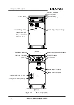
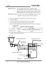
Connect the flexible hose from the compressor unit to the cryopump (See Figure 3-4) .
a.
Connect the helium gas supply flexible hose labeled SUPPLY to the helium gas
supply connector on the compressor. Then connect the other end of the hose to the
SUPPLY GAS port on the cryopump (coldhead).
b.
Connect the helium gas return flexible hose labeled RETURN to the helium gas
return connector on the compressor. Then connect the other end of the hose to the
RETURN GAS port on the cryopump (coldhead).
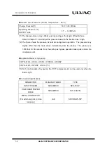
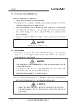
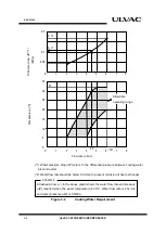
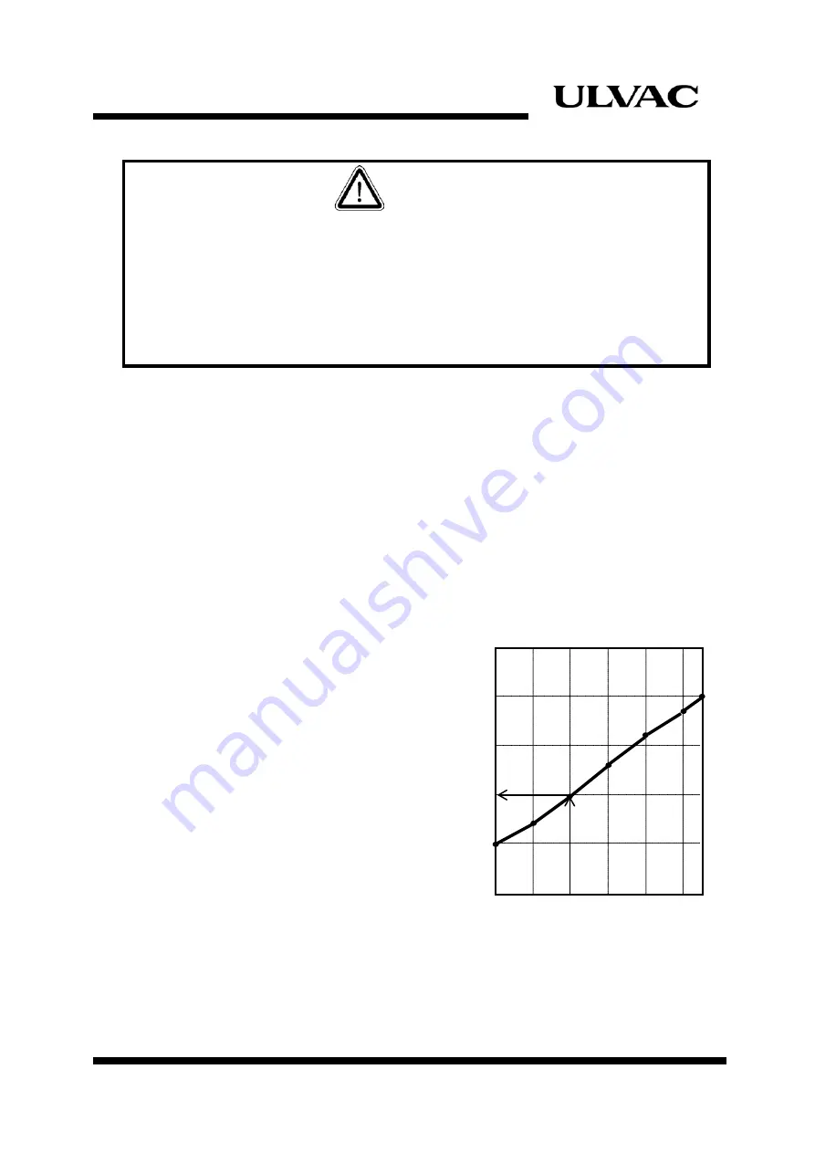
3. Check helium charge pressure.
Standard helium charge pressure
is 1.60
±
0.04MPaG at 20°C
.
See
Figure
3-3.
If the indicated pressure is higher
than appropriate, allow a slight
amount of helium gas to escape by
opening the gas charge valve
very
slowly
.
If indicated pressure is lower than
appropriate, add helium gas as
described in section 6.3.
Figure 3-3
Charge
Pressure and Temperature
CAUTION
C
har
ge P
res
s
ur
e
M
Pa
g
1.70
1.60
1.50
10
15
20
25
30
35 38
温
度
℃
Temperature (°C)
Summary of Contents for C15T
Page 2: ......
Page 8: ...F 6 ULVAC CRYOGENICS INCORPORATED This page intentionally left blank...
Page 14: ...S 4 ULVAC CRYOGENICS INCORPORATED This page intentionally left blank...
Page 16: ...IW 2 ULVAC CRYOGENICS INCORPORATED This page intentionally left blank...
Page 34: ...Operation 4 2 ULVAC CRYOGENICS INCORPORATED This page intentionally left blank...
Page 38: ...Disconnection and Storage 5 4 ULVAC CRYOGENICS INCORPORATED This page intentionally left blank...
Page 46: ...Maintenance 6 8 ULVAC CRYOGENICS INCORPORATED This page intentionally left blank...
Page 50: ...Troubleshooting A 4 ULVAC CRYOGENICS INCORPORATED This page intentionally left blank...
Page 54: ...Circuit Diagram B 4 ULVAC CRYOGENICS INCORPORATED This page intentionally left blank...
Page 57: ...Flexible Hose C 2 ULVAC CRYOGENICS INCORPORATED This page intentionally left blank...
Page 61: ...CS 2 ULVAC CRYOGENICS INCORPORATED This page intentionally left blank...
Page 63: ...Revisions R 2 ULVAC CRYOGENICS INCORPORATED This page intentionally left blank...


