Compressor Unit Instruction Manual
ULVAC CRYOGENICS INCORPORATED
6-5
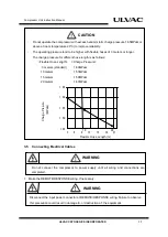
CAUTION
6.3 Charging Helium Gas
Equipment for charging helium gas (regulators, charging hoses, adopters) that can be used
at 2.0MPaG or above are required.
If the helium pressure gauge of the compressor unit shows 0 MPaG, contamination
caused by air or moisture may occur in the system. If it occurs, contact our Service
Engineering Division or customer support center.
When helium gas pressure reduces, it is necessary to add helium gas. Clarify the cause of
the pressure reduction before adding helium gas. If there is a leakage, take an adequate
measure before charging. Improperly connected self-sealing coupling might be one of the
causes of the leakage.
◇
It is recommended to use the regulator which shows the range of 4-6 MPaG as outlet
pressure.
◇
The gas charge inlet of the compressor unit is 1/4B male flare.
◇
Use helium gas with purity of 99.999% or above.
Follow the steps below to add helium gas;
1.
When mounting the regulator on a new helium bottle, perform the following
procedures in order to purge the air and fill helium gas in the gas line between the
regulator and the bottle valve.
a.
Open the regulator a little. The regulator can be opened commonly by turning the
handle clockwise.
b.
Slowly open the bottle valve, and purge the air in the gas line for several
seconds.
c.
Close the regulator. (Normally by rotating counterclockwise)
If the bottle valve is opened ignoring the above step 1, the air between the regulator and the
bottle valve diffuses into the helium bottle and deteriorates the purity of helium gas.
2.
Remove the front panel of the compressor unit.
3.
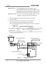
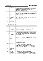
Connect the helium charging hose as follows:
CAUTION
Summary of Contents for C15T
Page 2: ......
Page 8: ...F 6 ULVAC CRYOGENICS INCORPORATED This page intentionally left blank...
Page 14: ...S 4 ULVAC CRYOGENICS INCORPORATED This page intentionally left blank...
Page 16: ...IW 2 ULVAC CRYOGENICS INCORPORATED This page intentionally left blank...
Page 34: ...Operation 4 2 ULVAC CRYOGENICS INCORPORATED This page intentionally left blank...
Page 38: ...Disconnection and Storage 5 4 ULVAC CRYOGENICS INCORPORATED This page intentionally left blank...
Page 46: ...Maintenance 6 8 ULVAC CRYOGENICS INCORPORATED This page intentionally left blank...
Page 50: ...Troubleshooting A 4 ULVAC CRYOGENICS INCORPORATED This page intentionally left blank...
Page 54: ...Circuit Diagram B 4 ULVAC CRYOGENICS INCORPORATED This page intentionally left blank...
Page 57: ...Flexible Hose C 2 ULVAC CRYOGENICS INCORPORATED This page intentionally left blank...
Page 61: ...CS 2 ULVAC CRYOGENICS INCORPORATED This page intentionally left blank...
Page 63: ...Revisions R 2 ULVAC CRYOGENICS INCORPORATED This page intentionally left blank...


