Maintenance
6-6
ULVAC CRYOGENICS INCORPORATED
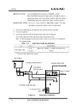
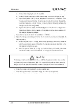
a.
Connect the charging hose to the regulator.
b.
Loosely connect the charging hose to the charge inlet on the compressor unit.
c.
Open the regulator until the return side pressure reaches 0.1 - 0.2 MPaG. Allow
helium gas to flow out from the charging hose for about 30 seconds. Meanwhile,
open the charge valve slightly in order to drive out the air that exists between the
charge valve and the charge inlet.
d.
Tighten the flair nut at the end of charging hose and close the charge valve.
Helium gas charge in the line between the regulator and the charge valve on the
compressor has been completed.
4.
Adjust the low pressure side of the regulator at 1.8 MPaG.
5.
Open the charge valve slowly and follow the instruction below based on the state of
the compressor.
a.
If the compressor unit is running under normal operating conditions, replenish it
with the pure helium gas until it reaches the operation pressure described in the
compressor instruction manual.
b. If the compressor unit is not running, replenish it with the pure helium gas until it
reaches the static pressure described in the compressor instruction manual.
If helium gas has been charged more than 1.9MPaG, the pressure relief valve on the
refrigerator may work. Charge helium gas slowly to prevent the pressure relief valve from
being activated. The pressure relief valve inside the compressor unit is set at 2.5MPaG.
6.
Close the charge control valve after charging helium gas.
7.
Close the regulator and remove the charging hose from the charge inlet.
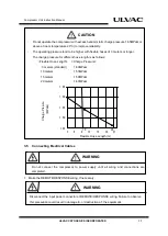
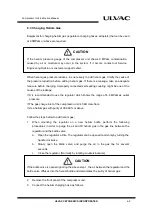
CAUTION
Summary of Contents for C15T
Page 2: ......
Page 8: ...F 6 ULVAC CRYOGENICS INCORPORATED This page intentionally left blank...
Page 14: ...S 4 ULVAC CRYOGENICS INCORPORATED This page intentionally left blank...
Page 16: ...IW 2 ULVAC CRYOGENICS INCORPORATED This page intentionally left blank...
Page 34: ...Operation 4 2 ULVAC CRYOGENICS INCORPORATED This page intentionally left blank...
Page 38: ...Disconnection and Storage 5 4 ULVAC CRYOGENICS INCORPORATED This page intentionally left blank...
Page 46: ...Maintenance 6 8 ULVAC CRYOGENICS INCORPORATED This page intentionally left blank...
Page 50: ...Troubleshooting A 4 ULVAC CRYOGENICS INCORPORATED This page intentionally left blank...
Page 54: ...Circuit Diagram B 4 ULVAC CRYOGENICS INCORPORATED This page intentionally left blank...
Page 57: ...Flexible Hose C 2 ULVAC CRYOGENICS INCORPORATED This page intentionally left blank...
Page 61: ...CS 2 ULVAC CRYOGENICS INCORPORATED This page intentionally left blank...
Page 63: ...Revisions R 2 ULVAC CRYOGENICS INCORPORATED This page intentionally left blank...


