ULVAC CRYOGENICS INCORPORATED
B-5/B-6
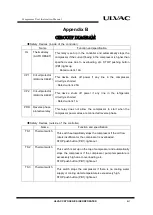
CN1
CN2
CP1
CP2
CR1
MC
MR
PRR
SOL
SW1
SW2
TM1
TM3
TM2
CR2
①
②
③
④
⑤
CN3
(CN4
55
1
6
3
7
MR
TM2
MC
4
10
8
1
6
2
TM1
11
CR1
TM2
R1
4
CN1
3
2
1
3
φ
50Hz
(
190
~
220V
)
3
φ
60Hz
(
200
~
230V
)
U
V
W
COMPRESSOR MOTER
ETM
TM3
CR2
R
E
T
S
MC
(R)
(W)
(BK)
OL
CP1
PRR
R
S
T
T
R
S
CR2
TM3
1-10
1-8
1-2
1-6
MC
14
13
1-11
1-6
1-10
TS1
③
④
PRR
TS2
⑥
⑤
CP2
TS3
⑧
⑦
NO
C
8
7
6
5
4
3
2-9
2-5
23
24
5
6
7
8
9
CN3
REMOTE
LOCAL
SW1
MC
CR1
CR3
41
42
PB1
⑫
OL
LPS
LOCAL
⑨
⑪
⑩
11
10
12
9
REMOTE
MC
96
32
95
31
CR3
3-13
3-14
2-13
2-14
S1
PL1
CR1
PL2
MC
(ORANGE)
(GREEN)
CR3
3-14
3-13
A1
A2
1-13
1-14
2-13
2-14
2-5
3-5
3-9
2-9
CN2
CP1-1
CP1-3
CP1-5
R1
S1
T1
CP1-2
CP1-4
CP1-6
(R)
(W)
(BK)
MC-1
MC-3
MC-5
(R)
(W)
(BK)
R2
S2
T2
MC-2
MC-4
MC-6
CR2-5
TM3-5
CR2-9
TM3-9
TM3-14
TM3-13
CR2-13
CR2-14
ETM-1
ETM-2
CP2-C
CN4-3
PB2
TM2-9
MC-23
CN4-7
PRR-5
3-9
3-5
1-9
1-5
TM2-5
MC-24
CN4-4
CN4-8
CN4-6
CN4-5
CP2-NO
MC-A1
MC-A2
CR1-6
CR1-10
TM2-14
TM2-13
MC-31
MC-32
MC-95
MC-96
CN4-12
CN4-11
CN4-9
MR-6
MR-1
MR-5
MR-3
MR-7
CR1-13
CR1-14
PB1-A
PB1-B
PB2-B
PB2-A
MC-14
MC-13
CR3-14
CR3-13
TM1-8
TM1-11
TM1-2
TM1-10
TM1-6
PRR-1
CR3-9
CR1-9
CR3-5
CR1-5
MC-42
MC-41
CN4-10
1
2
3
4
5
6
7
8
9
10
11
12
13
14
15
16
PB2
PB1
CN3
CR1
1-3
1-7
1-11
CR1-3
CR1-7
CR1-11
CP2-1
CP2-2
CP2
1
2
3
4
R1
S1
F1-1
F1-2
FUSE1
FUSE2
F2-1
F2-2
CP2-3
CP2-5
CP2-4
CP2-6
SOL
①
②
1
2
CN4-1
CN4-2
CR4
4-4
4-12
CR4-4
CR4-12
CR2-8
2-8
CR2
2-12
CR2-12
CR4-14
4-14
CR4
4-13
CR4-13
ETM
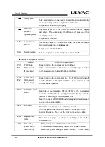
LPS
PB1(PL1)
PB2(PL2)
FUSE1,2
CR4
OL
TS1
TS2
TS3
Power connector
Coldhead Connector
External signal, Remote connector
Circuit protector
Circuit protector
Solenoid valve (SOL) Relay
Relay
Relay
Elapsed time meter
Fuse
Low pressure switch
Lighted STOP button (Orange)
Lighted START button (Green)
Magnetic conductor
Momentary power failure restart relay
Phase reversal protective relay
Solenoid valve
Remote/Local switch
L/H switch
OFF delay timer (set 5 sec.)
ON delay timer (set 5 sec.)
Solenoid valve (SOL) ON delay timer
(
set 30 sec.)
Thermal relay
Thermal protective switch (oil temperature)
Thermal protective switch (Compressor motor)
Thermal protective switch (Helium outlet)
wiring connector in terminal board)
Output signal relay for unit control
NOTES
◎:
CN3
(
For output signal, REMOTE)
Pin number shown in this box.
Wire color
:(
R
)
--red
、(
W
)
--white
、(
BK
)
--black
CP1 and CP2 are defaulted ON.
Coldhead output signal
Wire No.:
Terminal block No.:
○:
CN4 (Internal connector),
○
Pin number shown in this box. (Refer to wiring drawings for connectors)
PB2: Momentary button switch for 1a contact
PB1: Momentary button switch for 1b contact
Customers are required to supply switch and wiring.
Rated 220V, 5A recommended.
While coldhead is suspended, between 11 and 12 is conductive.
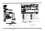
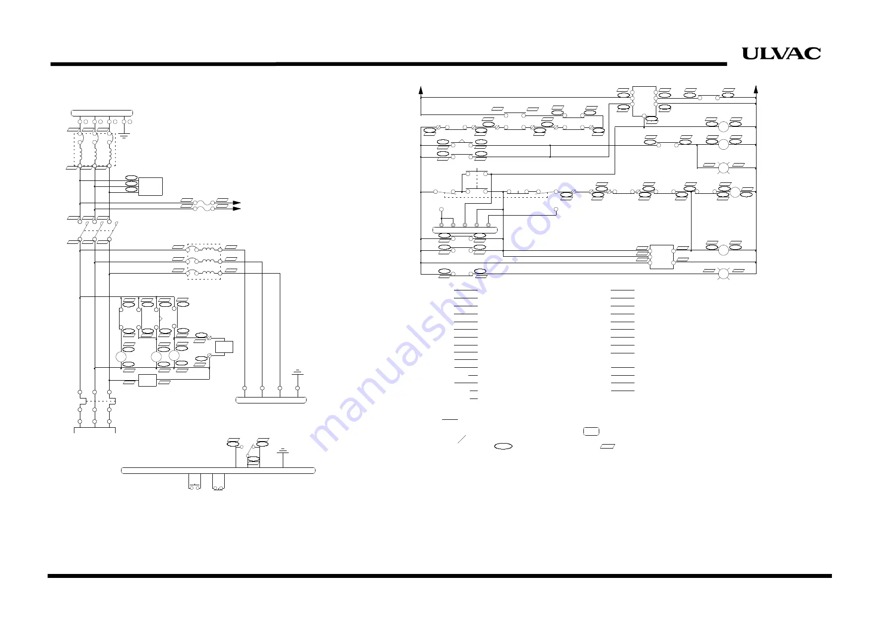
C15T CIRCUIT DIAGRAM
START STOP
COMPRESSOR MOTOR
Summary of Contents for C15T
Page 2: ......
Page 8: ...F 6 ULVAC CRYOGENICS INCORPORATED This page intentionally left blank...
Page 14: ...S 4 ULVAC CRYOGENICS INCORPORATED This page intentionally left blank...
Page 16: ...IW 2 ULVAC CRYOGENICS INCORPORATED This page intentionally left blank...
Page 34: ...Operation 4 2 ULVAC CRYOGENICS INCORPORATED This page intentionally left blank...
Page 38: ...Disconnection and Storage 5 4 ULVAC CRYOGENICS INCORPORATED This page intentionally left blank...
Page 46: ...Maintenance 6 8 ULVAC CRYOGENICS INCORPORATED This page intentionally left blank...
Page 50: ...Troubleshooting A 4 ULVAC CRYOGENICS INCORPORATED This page intentionally left blank...
Page 54: ...Circuit Diagram B 4 ULVAC CRYOGENICS INCORPORATED This page intentionally left blank...
Page 57: ...Flexible Hose C 2 ULVAC CRYOGENICS INCORPORATED This page intentionally left blank...
Page 61: ...CS 2 ULVAC CRYOGENICS INCORPORATED This page intentionally left blank...
Page 63: ...Revisions R 2 ULVAC CRYOGENICS INCORPORATED This page intentionally left blank...


