Compressor Unit Instruction Manual
ULVAC CRYOGENICS INCORPORATED
D-1
Appendix D
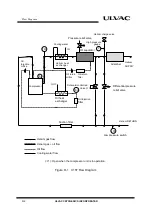
FLOW DIAGRAM
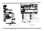
Low pressure helium gas returning from the refrigerator unit enters the compressor.
Lubricant oil is injected into the compressor with the low pressure helium; the gas
containing the oil is then compressed by the compressor pump turning it into high
temperature high pressure helium gas. Most of the lubricant oil returns to droplet form
and is separated within the compressor. This lubricant oil is pooled at the bottom and
lubricates the inside of the compressor. It follows the circulating system where it comes
out from the compressor and cooled down at an oil heat exchanger before being injected
back into the compressor through an oil injection filter.
High temperature high pressure helium gas comes out from the compressor, passes
through a water cooled helium heat exchanger for removal of compression-caused heat. It
is cooled to an ambient temperature and then enters an oil separator. In here, the oil is
separated and the droplets of separated oil pass thorough an oil return filter and oil
return orifice before joining the low pressure helium gas and being returned to the
compressor. High pressure helium gas comes out from the oil separator enters an
adsorber where oil-mist is adsorbed and removed. The Helium gas comes out the
adsorber passes through a flexible hose and is supplied to the refrigerator unit.
Summary of Contents for C15T
Page 2: ......
Page 8: ...F 6 ULVAC CRYOGENICS INCORPORATED This page intentionally left blank...
Page 14: ...S 4 ULVAC CRYOGENICS INCORPORATED This page intentionally left blank...
Page 16: ...IW 2 ULVAC CRYOGENICS INCORPORATED This page intentionally left blank...
Page 34: ...Operation 4 2 ULVAC CRYOGENICS INCORPORATED This page intentionally left blank...
Page 38: ...Disconnection and Storage 5 4 ULVAC CRYOGENICS INCORPORATED This page intentionally left blank...
Page 46: ...Maintenance 6 8 ULVAC CRYOGENICS INCORPORATED This page intentionally left blank...
Page 50: ...Troubleshooting A 4 ULVAC CRYOGENICS INCORPORATED This page intentionally left blank...
Page 54: ...Circuit Diagram B 4 ULVAC CRYOGENICS INCORPORATED This page intentionally left blank...
Page 57: ...Flexible Hose C 2 ULVAC CRYOGENICS INCORPORATED This page intentionally left blank...
Page 61: ...CS 2 ULVAC CRYOGENICS INCORPORATED This page intentionally left blank...
Page 63: ...Revisions R 2 ULVAC CRYOGENICS INCORPORATED This page intentionally left blank...

