background image


05 


<Operation> 

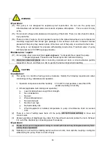
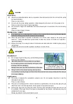
(14)   This  pump  is  not  designed  for  explosion-proof  construction.  Do  not  use  the  pump  near 

inflammables such as flammable solvent and in explosive atmosphere.    There is a risk of injury 

or fire. 

(15)   Do not insert a finger and substances into opening of the motor. There is a risk of electric shock, 

injury and a fire. 

(16)   There is a risk of rupture. Do not operate the pump in the status that exhaust vent is blocked or 

mounting  equipment  that  hinder  gas  passage  in  the  exhaust  vent  side.  Increased  internal 

pressure of the pump may cause rupture of the main unit of the pump or overload to the motor. 

This  pump  is  not  designed  for  pressure  withstanding  construction.  Threshold  value  of  pump 

internal pressure is 0.03 MPa (gauge pressure). 

<Maintenance / repair>


(17)   Do not allow other personnel than 

repair engineers


*

to disassemble or repair the pump. 

* 1 Repair engineers: Those who are trained by ULVAC technical training. 

(18)   Wear  dust  mask  and  gloves  when  conducting  replacement  work.  A  minute  abrasive  particle 

suspends in the air, and there is a risk to go into the human body when breathing.


<Installation> 

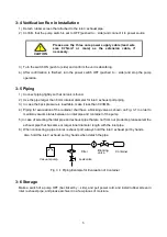
(1)    This  pump  is  a  machine  having  precise  clearance.  Satisfy  the  following  requirements  when 

conducting storing, installation and operation 


1.    Operation temperature and the humidity 

0

 to 40

 in temperature, Lower than 85% 

(relative humidity) in humidity 

2.    Others (applicable both storing and operation) 

a.   

Level location where enough floor strength. 

b.   

No condensation. 

c.   

No dust. 

d.   

Well ventilated indoor. 

e.   

No explosive gas. 

f.   

No direct sun rays. 

g.   

No flammability risk. 

h.   

When  Equipment  is  installed,  temperature  in  pump  circumference  shall  not  exceed 
40


(2)    There  is  a  risk  of  hurting  lower  back.  Lift  the  pump  with  both  hands  definitely  to  move  and     

conduct work. 

(3)    Abrasive particles of diaphragm may drain from the exhaust vent and pollute the room. Exhaust 

it to out of the chamber by connecting pipes if necessary. 

<Operation> 

(4)    Please do not use it to application coming in contact with human body transplant and body fluid / 

a living body organization. 

(5)    Definitely do not touch the rotating section such as a motor, main spindle, coupling, cooling fan 

while driving the pump. There is a risk of injury.


WARNING     

CAUTION     

Summary of Contents for DA-41D

Page 1: ...ion Manual before starting the pump in order to use the pump effectively and safely Please keep this Instruction Manual carefully We reserve our right to change dimensions or specifications of the mot...

Page 2: ...4 3 3 Installation location 4 3 4 Verification Run in Installation 5 3 5 Piping 5 3 6 Storage 5 4 Caution in Operation 6 4 1 Caution in Operation 6 4 2 When Thermal Protector Operated 6 4 3 Starting...

Page 3: ...g List Fig 2 1 DA 41D DA 81S Appearance 3 Fig 2 2 DA 41DK DA 81SK Appearance 3 Fig 3 1 Piping Example for Evacuation of Container 5 Table 1 1 Equipment Specifications 1 Table 6 1 Consumable Parts List...

Page 4: ...rrectly Always read Directions to use safely in particular Storage of Instruction Manual Please keep Instruction Manual carefully After reading store this Instruction Manual on the location where avai...

Page 5: ...t pipe 2 pcs Power plug adapter attached to power cord 1 pcs 3 Whether damaged positions are found 4 Whether loosen external screws or inlet exhaust pipe Whether coming off positions are found In case...

Page 6: ...st injuries of users Incorrect operation may result in possibility to cause death or heaviest injuries of users Incorrect operation may result in possibility to cause death or heaviest injuries of use...

Page 7: ...pair definitely There is risk of electric shock or injury attributed to sudden start of the pump 5 Conduct wiring work correctly by observing Electric System Design Standard and the in house rules Inc...

Page 8: ...rticle suspends in the air and there is a risk to go into the human body when breathing Installation 1 This pump is a machine having precise clearance Satisfy the following requirements when conductin...

Page 9: ...s a risk of burn Installation 1 Do not apply impact to the pump and not falling sidelong There is a risk of failure 2 DA 41DK DA 81SK to the customer of purchase Do not hold or push the tube at the to...

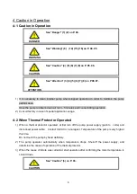
Page 10: ...ambient temperature in range of 0 to 40 If the temperature was over 40 degrees put a cooling fan or similar device to cool it down to the ambient temperature If operated in high temperature life of t...

Page 11: ...ed regardless description in the followings Acetone Ethyl ether Ethyl acetate Flora and fauna oil etc 5 Never absorb the gas that mixed dust dust moisture 6 Do not operate long time in environment nea...

Page 12: ...e by shutting the power supply to the motor automatically when rotation stops during operation due to pump failure or current supplied to the motor exceeded due to overload 2 It is recommended to adop...

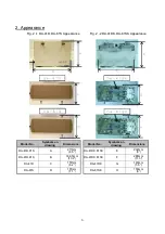
Page 13: ...1SK Appearance Model No Symbols on drawing Dimensions Model No Symbols on drawing Dimensions DA 41D 81S A 217mm 8 5 DA 41DK 81SK E 202mm 8 DA 41D 81S B 336 5mm 13 2 DA 41DK 81SK F 288mm 11 3 DA 41D C...

Page 14: ...sun rays g No flammability risk h When Equipment is installed temperature in pump circumference shall not exceed 40 104 degF 3 3 Installation location Select a location where dust and moisture are sm...

Page 15: ...s shown on Fig 3 1 in order to maintain vacuum status between an inlet pipe and container of the pump 5 In case of selecting the inlet pipe and exhaust pipe that are not from our products please selec...

Page 16: ...sh to side and disconnect power cable Contact ULVAC or local agent Temperature of the pump is very high at this time Do not touch the pump by hand definitely 2 The pump operates automatically when tem...

Page 17: ...follow the procedure described below 1 Open the inlet port to atmosphere and repeat switch ON OFF two or three times until the pump starts If still it does not start warm up the ambient temperature t...

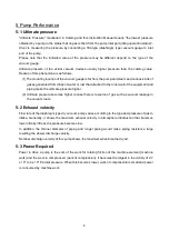
Page 18: ...and piping make the ultimate pressure higher 2 Ultimate pressure becomes higher in case there is resource of gas such as vacuum leakage in the vacuum route 5 2 Exhaust velocity Flow rate of the diaph...

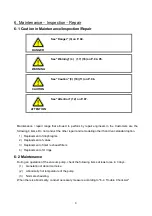
Page 19: ...acement of valves 3 Replacement of inlet exhaust filters 4 Replacement of O rings 6 2 Maintenance During an operation of the vacuum pump check the following items at least once in 3 days 1 Generation...

Page 20: ...etic rubber EPDM PTFE affixed 9 000hr Valve A 3 2 PTFE 9 000hr Valve B 1 2 PTFE 9 000hr Valve holder A 2 2 EPDM 9 000hr Valve holder B 1 2 SUS 9 000hr Inlet exhaust filter 2 3 Urethane cellular porous...

Page 21: ...oled down 2 Wear a dust mask and gloves when replacing diaphragms and valves A minute abrasive particle suspends in the air and there is a risk to go into the human body when breathing 3 Wear gloves w...

Page 22: ...panel Photo 3 4 Remove 8 pcs of hexagon socket head cap screw M6 x 25 and detach the pump head Photo 4 5 5 Pull connecting tube from the valve retainer and separate the pump head of left and right Pho...

Page 23: ...lvent cleanly 10 Apply small quantity of vacuum grease on hexagon socket head cap screws M8 x 18 portion on back of the new diaphragm to prevention of scoring of a screw and mount it on the connecting...

Page 24: ...et exhaust pipe Photo 1 1 2 In case of DA 41DK 81SK Replace the diaphragm according to the procedure for 1 1 DA 41D 81S 4 to 13 Hexagon socket head cap screw M6 x 25 As shown in Photo 10 Good example...

Page 25: ...ad similarly Photo 14 3 Detach valve plate No adhesive screws are used for mounting the valve plate Valve plate can be detached easily by hands since the valve plate is simply embedded in a circular f...

Page 26: ...16 4 Detach used valves Photo 16 5 Clean the pump head and the valve retainer with solvent When clean pump heads clean both faces of the valve surface side and diaphragm side...

Page 27: ...position shown by the above Photo one by one Mount to arrow position Valve mounting 4 Mount valve holder A to the position shown by the above Photo one by one Valve mounting 5 Mount valve plate to th...

Page 28: ...d top panel Procedure is the same as 14 to 16 of 1 replacement of Diaphragm Be careful not to make a mistake in type number of sheets Photo 17 There is no front and back control in valve mounting Moun...

Page 29: ...cedure is the same as 1 to 2 of 2 replacement of valves 2 Detach used inlet exhaust filter Photo 18 3 Clean filter mounting portion of valve retainer with solvent 4 Mount new inlet exhaust filter acco...

Page 30: ...ing S 28 Photo 19 4 Disassemble the horse nipple Spanish yellow and remove the O ring S 4 Photo 19 upper right drawing 5 Disassemble inlet exhaust pipe from valve retainer and remove O ring P 10A 3 pc...

Page 31: ...rease slightly on the entire new O rings S 28 P 10A and embed to each mounting portion 9 Mount each part Procedure is the same as 7 to 8 of 2 replacement of valves 5 Replacement of bearing Request Ulv...

Page 32: ...SUS 19 Valve holder B SUS 20 Pin for pump head PTFE 20 Pin for pump head PTFE 21 Inlet exhaust filter Urethane cellular porous medium 21 Inlet exhaust filter Urethane cellular porous medium 22 Nipple...

Page 33: ...inspection of pump head 15 Abnormal bearing 15 Replacement 6 4 16 Miscellaneous Damage of pump internal parts 16 Overhaule replacement of damaged parts 6 4 Pressure failed to drop 1 Pump is small for...

Page 34: ...the status that absorption gas pressure is high 1 Do not conduct continuous operation in vicinity of atmospheric pressure 2 Absorption gas is high temperature 2 Mount refrigerating machine such as gas...

Page 35: ...e and inspection etc d Malfunctions caused by modifications or repairs carried out by a party other than the manufacturer or by a service company not approved by the manufacturer e Malfunctions caused...

Page 36: ...Industrial Safety and Health Law designates particular substances as the materials to be notified 2 Usage Status Operation Method Approx hours per day years and months Continuous Operation Intermitte...

Page 37: ...6 6397 2286 ULVAC KIKO Inc https ulvac kiko com en Please contact us for products Service Base or other Inquiries from here ULVAC Inc Components Division 2500 Hagisono Chigasaki Kanagawa 253 8543 Japa...

Reviews: