background image


20


9. Conclusion 

This manual contains only general information about pump operation. Therefore, 
if you come up with any question or trouble, contact our representative or ULVAC 
KIKO. 
 

Warranty 


(1) The warranty for this pump (this equipment) extends for a period of one year from the date of 

shipment. 

(2)  Any  malfunctions  or  defects  which  occur  under  normal  usage  conditions  during  the  warranty 

period will be repaired free of charge. 

Note,  the  warranty  stated  here  is  an  individual  warranty  covering  the  pump.  In  addition,  the 
scope of the warranty coverage concerning repairs is limited to the repair and/or replacement of 
parts. 
Normal usage conditions refer to the following: 

a) Ambient temperature and humidity during operation: 0 - 40

°

C, below 85% RH 

b) Operation in accordance with the user manual 

(3) Repair fees will incur during the warranty period for the following cases: 

a) Malfunctions due to a natural disaster or fire. 
b) Malfunctions caused by special atmospheric conditions, such as salt damage, inflammable 

gas, corrosive gas, radiation or pollution. 

c)  Malfunctions  caused  by  usage  conditions  that  differ  from  those  stated  in  the  user  manual 

(performance specifications, maintenance and inspection, etc.). 

d)  Malfunctions  caused  by  modifications  or  repairs  carried  out  by  a  party  other  than  the 

manufacturer, or by a service company not approved by the manufacturer. 

e) Malfunctions caused by noise (electric disturbance). 
f) Malfunctions that occur when not using a rated power supply. 
g) Malfunctions that occur when there is an abnormal rise in internal pressure due to the pump 

exhaust outlet being blocked during operation, etc. 

h) Malfunctions that occur, when the pump is damaged as a result of being dropped or falling, 

etc. 

i) Malfunctions which are determined by the manufacturer

s technical personnel to be caused 

by conditions that do not comply with the usage conditions for this vacuum pump. 

j) Malfunctions due to the replacement of consumables.         

(4) Disclaimer 

a)  We  shall  not  be  liable  for  any  malfunctions  of  our  products  caused  by  the  customer, 

regardless if the malfunction does not fall within the warranty period, nor shall we be liable 
for any loss of opportunity for the customer

s clients or for compensation for any damages to 

other products, labor costs, production loss, transportation expenses and other related work.   

b)  We  shall  not  be  liable  for  any  claims  and  patent  infringements,  including  secondary 

damages, filed a claim by a third party against the customer.


Summary of Contents for DAP-6D Series

Page 1: ...o Users Please read this manual thoroughly to ensure safe and effective use of the equipment Keep this manual in a safe place Due to periodic improvements in performance the equipment described in thi...

Page 2: ...Drawing 8 5 Installation and Operation 9 6 Cautions in Operation 11 6 1 Cautions in Operation 11 6 2 Startup in Cold Season 11 6 3 Thermal Protector 11 7 Maintenance Inspection and Repair 12 7 1 Caut...

Page 3: ...equipment correctly Read the section on Safe Use particularly closely Keep This Manual in a Safe Place After reading this manual be sure to keep it in a safe place which is readily accessible to other...

Page 4: ...ge to the equipment and hinder its correct operation Cautions for Safety in Use Applications 1 This pump is not designed to be explosion proof and should therefore not be used to discharge explosive g...

Page 5: ...d Failure to earth the pump correctly may result in electric shock if a fault or earth leakage occurs 8 Use the pump only at the rated voltage Use at other than the rated voltage will interfere with o...

Page 6: ...e for each motor component is within the requirements for class of motor insulation as legally required in your country Installation 1 The fine clearances used in this pump require that the following...

Page 7: ...injury Maintenance and Repair 10 Ensure that the pump is discarded in accordance with appropriate legislation related to the treatment and cleaning of waste products Ensure that the pump is discarded...

Page 8: ...outlet is free of back pressure when the pump is started Back pressure at the pump outlet will result in overload on the motor and may prevent starting 9 The overload protector operates when the pump...

Page 9: ...rature or gases of equivalent characteristics 4 Do not attempt to discharge gases containing particles dust water or corrosive gases 5 Do not operate the pump for long periods at near atmospheric pres...

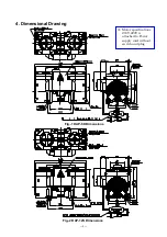
Page 10: ...8 4 Dimensional Drawing Fig 1 DAP 6D Dimensions Fig 2 DAP 12S Dimensions Motor specifications 200V 220V is attached to Power supply cord without switch and plug...

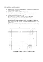
Page 11: ...ssembling the pump in a system Pay an attention particular to the ambient temperature 0 C 40 C Float the pump from the system using a rubber shock absorber install the pump so that vibration is not tr...

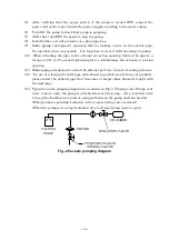
Page 12: ...force could damage the exhaust or suction opening 11 Make piping arrangement so that the exhaust port tree tram is a backing pressure 12 In case of selecting the inlet pipe and exhaust pipe that are n...

Page 13: ...ot restart To restart it vent the pump to atmospheric pressure If the pump is used for other applications consult with us 6 2 Startup in Cold Season In a cold season it may sometimes be difficult to s...

Page 14: ...The following checks are required at least once every three days during operation 1 Check for abnormal noises 2 Check for abnormal heating of the pump 3 Check that gas is discharged normally If a prob...

Page 15: ...Diaphragm Deformation crack and hardening Visual check Suction exhaust valve Deformation and crack Visual check Head gasket Damage and leak Visual check Bearing Unusual sound Auditory check disposal...

Page 16: ...loosening agent for screws Replacing diaphragm Loctite 242 or Loctite 243 Replacing valve Loctite 262 or Loctite 263 5 Rag 6 Solvent for wiping something that has no effect on rubber such as ethanol 7...

Page 17: ...valve The picture shown is the primary side of the DAP 12S but the procedure is the same for the secondary side of the DAP 12S and both the primary and secondary sides of the DAP 6D Step 3 Remove the...

Page 18: ...cting rod Concave positioning guide Convex positioning guide Step 5 Using the torque screwdriver 4 0 Nm and the small flat head screw M5 12 fasten the diaphragm and the push plate for the diaphragm al...

Page 19: ...the dent No gap Suction side Step 7 Using the torque screwdriver 0 25 0 30 Nm with the tri wing bit attached fasten the valve aligned in Step 6 with the tri wing screw M3 4 Apply the Loctite 262 or L...

Page 20: ...sure to always follow the appropriate tightening torque Failure to do so can lead to product damage Align the notches to the pins Small flat head screw Step 10 Attach the pump head First using connect...

Page 21: ...40 C range 10 Starting the pump in case its inside is vacuum pressure Vent pump to atmospheric pressure Unusual sound 1 Bearing damaged Replace 2 Diaphragm broken Replace 3 Motor damaged Replace Inad...

Page 22: ...anual performance specifications maintenance and inspection etc d Malfunctions caused by modifications or repairs carried out by a party other than the manufacturer or by a service company not approve...

Page 23: ...Industrial Safety and Health Law designates particular substances as the materials to be notified 2 Usage Status Operation Method Approx hours per day years and months Continuous Operation Intermitte...

Page 24: ...6 6397 2286 ULVAC KIKO Inc https ulvac kiko com en Please contact us for products Service Base or other Inquiries from here ULVAC Inc Components Division 2500 Hagisono Chigasaki Kanagawa 253 8543 Japa...

Reviews: