background image


No. 21510-2-01-6 


DIAPHRAGM DRY VACUUM PUMP


MODEL   

DAT-50DEP, DAT-100SEP


Prior to use


For safe and efficient use of this pump, please read this 

manual carefully before operation. 

After reading the manual, keep it in your file for future 

reference. 

Specifications in this manual are subject to change without 

notice due to    future improvement. 


ULVAC KIKO. Inc. 


INSTRUCTION MANUAL


Summary of Contents for DAT-50DEP

Page 1: ...or safe and efficient use of this pump please read this manual carefully before operation After reading the manual keep it in your file for future reference Specifications in this manual are subject t...

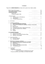
Page 2: ...Electric Wiring 3 3 5 Fluctuations in the power voltage and frequency 4 3 6 Checking Operation After Installation 5 3 7 Piping 5 3 8 Storage 5 4 Cautions for Operation 5 4 1 Cautions for Operation 5 4...

Page 3: ...3 Change region of the voltage and frequency 4 Fig 4 Example of Piping Used When Evacuating a Vessel 5 Table 1 Product Specifications 1 Table 2 Protector Specifications 6 Table 3 Consumables List 7 T...

Page 4: ...quipment correctly Read the section on Safe Use particularly closely Keep This Manual in a Safe Place After reading this manual be sure to keep it in a safe place which is readily accessible to others...

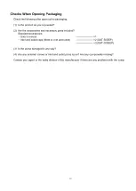
Page 5: ...ry parts included Standard accessories User s manual 1 Inlet and outlet caps fitted to inlet and outlet 2 DAT 50DEP 3 DAT 100SEP 3 Is the pump damaged in any way 4 Are any external screws or inlet and...

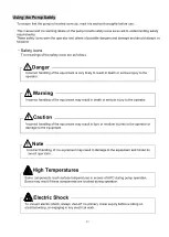
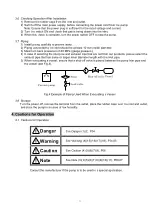
Page 6: ...y to the operator Incorrect handling of the equipment may result in death or serious injury to the operator Incorrect handling of the equipment may result in light or medium injuries to the operator o...

Page 7: ...t the relevant wiring is in accordance with technical standards for electrical equipment and wiring regulations Incorrect wiring may result in fire 6 Remove the power cord from the terminal before con...

Page 8: ...manufacturer 20 To prevent ingestion of microscopic particles resulting from wear of components use a dust mask and gloves during repair work Installation 1 The fine clearances used in this pump requi...

Page 9: ...peration turn power OFF immediately to prevent accidents remove the power cord from the terminal and contact your dealer or the manufacturer for inspection and repair 13 Leave the pump for at least 30...

Page 10: ...mp is starting may overload the motor 10 The thermal protection relay operates when the pump reaches a very high temperature Touching the pump in this condition may result in burns Maintenance and Rep...

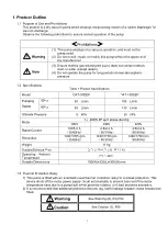
Page 11: ...100 L min 60Hz 55 L min 110 L min Ultimate Pressure 5 kPa 20 kPa Motor 1 200W 4P split phase starting 100V 200V 220V Rated Current 5 6 5 0 A 50 60Hz 2 8 2 4 A 50 60Hz 2 6 2 2 A 50 60Hz Revolution 142...

Page 12: ...2 2 Dimensions Fig 2 DAT 100SEP Dimensions Fig 1 DAT 50DEP Dimensions...

Page 13: ...a vacuum pump directly on the base Employ anti vibration rubber between the base and the vacuum pump 3 3 Location The pump should be installed level in a location with minimal dust and humidity This l...

Page 14: ...nd to the voltage change and frequency change in Domain B it shall operate with main rated values and shall be used practically convenient However operation with it is convenient and safe is maintaine...

Page 15: ...et pipe and exhaust pipe that are not from our products please select the exhaust pipe that has same or larger inner diameter length with the inlet pipe 5 When evacuating a vessel ensure that a shut o...

Page 16: ...ture for a little while and then turn on the power again 2 With the inlet open to atmosphere run the pump for a few minutes to warm it 3 Commence normal operation once the pump has warmed 5 Pump Perfo...

Page 17: ...gular Inspections Inspect consumables after the first 6000 hours of operation and replace and clean in accordance with the Replacement and Cleaning Guide on the following page Refer to 6 4 Replacing a...

Page 18: ...ion Suction Exhaust valves Deformation crack Visual inspection Bearing Abnormal noises Listen 6 4 Replacing and Cleaning Consumables See Warning 20 P05 See Caution 11 12 P06 The pump becomes very hot...

Page 19: ...tite 242 Use items No 5 and 6 to wipe down any dirty area when replacing the part Part Replacement Procedure Definition of Terms In the replacement procedure the terms primary side and secondary side...

Page 20: ...2 remove 1 the small pan head screws w M4 12 SW Qty 5 then remove 2 the pump head cover 3 the pump head gasket and 4 the filter Next remove 5 the small pan head screws M3 5 and then remove 6 the air...

Page 21: ...hed in Step 5 Apply Loctite 242 onto 3 to 4 threads of the screw tip for the small flat head screws M5 12 Then tighten the screws in order 1 through 4 makes 3 passes and partially tightening each on e...

Page 22: ...aries depending on the primary side the secondary side and the model Therefore check the picture below for the position to avoid making a mistake during the attachment In addition apply the Loctite 24...

Page 23: ...the attachment attach the parts following the same location as indicated in the picture below In addition be sure to insert the filter all the way so it does not come out or get stuck DAT 100SEP Prima...

Page 24: ...ing at it from the exhaust suction outlet Use the torque screwdriver No 2 2 0 Nm when tightening the small pan head screws w M4 12S Qty 5 Tighten the screws in order from 1 to 5 In addition make two p...

Page 25: ...ake two passes around 1 through 4 when tightening the screws to ensure proper tightening Do the same for Steps 7 through 12 on the opposing pump head Be sure to always follow the appropriate tightenin...

Page 26: ...sel 1 Select another pump 2 Pressure measurement is incorrect 2 Measure the pressure correctly 5 1 Pressure does not diminish 3 Vacuum gauge is unsuitable 3 Measure with a calibrated vacuum gauge suit...

Page 27: ...e and inspection etc d Malfunctions caused by modifications or repairs carried out by a party other than the manufacturer or by a service company not approved by the manufacturer e Malfunctions caused...

Page 28: ...Industrial Safety and Health Law designates particular substances as the materials to be notified 2 Usage Status Operation Method Approx hours per day years and months Continuous Operation Intermitte...

Page 29: ...6 6397 2286 ULVAC KIKO Inc https ulvac kiko com en Please contact us for products Service Base or other Inquiries from here ULVAC Inc Components Division 2500 Hagisono Chigasaki Kanagawa 253 8543 Japa...

Reviews: