DC Power Supply
【
DC-10-D/DC-20-D/DC-10-DH/DC-20-DH
】
5. How to Operate
-32-
③
The current operation mode is displayed.
LOCL:
Select this for use in the LOCAL mode.
HOST
:
Select this for use in the HOST mode.
USER
:
Select this for use in the USER mode.
HST+
:
Select this for use in the HST+ mode.
CSTM
:
Select this for use in the CSTM mode.
④
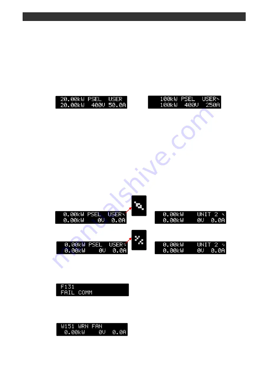
The current output value is displayed in the order of the output power, voltage, and current from the
left.
Single unit
In P/S connection
Power:
At 100kW or more in the P/S setting mode, the figures after the first decimal
place are not displayed.
Current:
At 100A or more in the P/S setting mode, the figures after the first decimal
place are not displayed.
* With the P/S connection established, a connection mark appears at the upper right of the screen.
When the mark is connected, the P/S connection is established whereas when the mark is not
connected, the P/S connection is not established.
If the marks are not connected, check the the P/S cable for connection.
For a secondary unit, the unit number appears at the upper right of the screen.
In addition, constant voltage control in output control mode cannot be used when P/S is connected.
With P/S connection established
UNIT1
UNIT2
With no P/S connection established
UNIT1
UNIT2
・
When a FAIL occurs, the ERROR code is displayed at the top of the screen and the FAIL name is
displayed at the bottom.
For details, see Table 4-11 in [4-14 Display of ERROR code on front panel].
・
When a WARNING occurs, the ERROR code and WARNING name are displayed at the top of the
screen.
For details, see Table 4-12 in [4-14 Display of ERROR code on front panel].
Summary of Contents for DC-10-D
Page 87: ......


