DC Power Supply
【
DC-10-D/DC-20-D/DC-10-DH/DC-20-DH
】
5. How to Operate
-37-
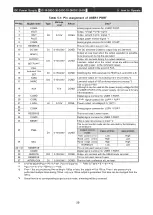
5-2-2 Pin assignment of USER2 PORT
The pin assignment of USER2 PORT is as follows:
For wiring, connect with an external control device, such as a PLC, in reference to the [Table 5-4:
USER2 PORT connection equivalent circuit] section.
USER2 PORT is a PORT that extracts only I/O for some inputs and outputs from 37-pin USER1 PORT.
It can be used when operations need to be separated, for example when obtaining values from HOST
but operating outputs from USER2 PORT. It can also be used as an RS-485 serial communication port
by connecting only Pin 5, Pin 7, and Pin 8.
Table 5-3: Pin assignment of USER2 PORT
Pin No.
Signal name
Type
Voltage
level
Return
Detail
1
INTERLOCK
DI
0-15V/24V
GND
Interlock released at Low.
2
SETPOINT
DO
0-15V/24V
GND
Low when the output values are within a certain range with
respect to the command values.
3
DC ON
DI
0-15V/24V
GND
DC output at Low.
4
OUTPUT
DO
0-15V/24V
GND
Low during output operation.
5
GND
Digital signal common for USER2 PORT.
GND for RS-232C, RS-485 signals. *1
6
RESERVE
This is not used. Leave it open.
7
TXD+/RXD+
GND
Positive (-) signal of RS-485 differential signal. *2
8
TXD-/RXD-
GND
Negative (-) signal of RS-485 differential signal. *2
9
AUX
0-15V
GND
The output is 15V.
Although it can be used as the power-supply voltage for DO of
USER2 PORT of the power supply, do not use it for any other
purposes.
*1. Be sure to connect GND eartch.
*2. When using RS-485, it is recommended to use a twisted pair for the signal wiring on the + and - sides.
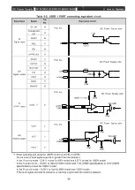
Table 5-4: USER 2 PORT connecting equivalent circuit
Signal type
Signal
Pin No.
Equivalent circuit
DI
Digital input
INTERLOCK
1
DC-10-D/DC-20-D側
PLC等
+15V
DI
3.3kΩ
DC ON
3
DO
Digital output
SETPOINT
2
DC-10-D/DC-20-D側
PLC等
100Ω
1000p
COMD
DO
COM
OUTPUT
4
DC Power Supply side
DC Power Supply side
PLC etc.
PLC etc.
Summary of Contents for DC-10-D
Page 87: ......


