DC Power Supply
【
DC-10-D/DC-20-D/DC-10-DH/DC-20-DH
】
5. How to Operate
-38-
5-2-3 Recommended digital I/O connection circuit
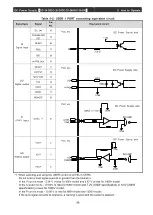
Fig. 5-1 shows the recommended USER IO PORT digital I/O connection circuit.
COMD / GND
+15V
3.3kΩ
AD
INTERFACE
DC Power Supply
DI
Digital input
DI
1.0kΩor less
+15V/+24V
DO
COMD / GND
DO
Digital output
100Ω
1.3kΩ~4.7kΩ
COMD / GND
PLC etc.
COMD / GND
AUX +15V
DO
COMD / GND
DO
Digital output
100Ω
1.3kΩ~2.4kΩ
When using AUX of the power supply.
When not using the AUX of the power supply.
Figure 5-1: Recommended USER IO PORT digital I/O connection circuit
5-2-4 Precautions for wiring of USER IO PORT
For wiring of USER IO PORT, you are recommended to follow the procedure below since noise may be
caused.
(1) Use of a twisted shield pair wire
(2) Insulation of signals by photocouplers etc. on the side of external connection devices
(3) Signal wires shall be arranged without tying with a power line.
(4) Connection in the shortest distance
Table 5-5: Electrical specifications of signals
●
Digital signal
(Photo coupler)
Digital signal input (DI)
15V/24V
Drive current: 2 mA or more
Digital signal output (DO)
15V/24V
Drive current: 5 mA to 20 mA/1ch
●
Analog signal
Analog signal input (AI)
0
~
10V
Input impe
dance: 100 kΩ or more
Analog signal output (AO)
0
~
10V
Output current: 5 mA or less
Table 5-6: Scale of analog signal output (AO)
DC-10-D
DC-20-D
Analog signal output range
Voltage
0
~
1500V
0
~
1500V
0V
~
10V
Current
0
~
25A
0
~
50A
0V
~
10V
Power
0
~
10kW
0
~
20kW
0V
~
10V
* This depends on "the value of a single unit" × "the number of units."
(Refer to Table 4-6 in Item 4-6)
Summary of Contents for DC-10-D
Page 87: ......


