background image


iv 


YK18-0012-AI-101-02


This  product  is  shipped  after  strict  internal  inspection.  If  you  find  any  manufacturing  defects, 
accidents during the transportation, or other defects attributed to our responsibility, please contact 
our  Components  Division  at  headquarters  or  the  nearest  sales  office  or  agency.  The 
repair/replacement is free of charge. 


Warranty Product 

(a) Turbo-molecular-pump pumping system Desktop YTP (YTP70 A-D)


Warranty Period


(a) Domestic: 1 year from the date of delivery. 

(b) Direct export: 1 year from the date of B/L. 


Warranty Coverage 

(a) Domestic: 

For a product at the time of delivery with a damage because of trouble during 
transportation.   
For a product not satisfying the basic specification in spite of using the product within the 
service condition (temperature range, power supply, etc). 


(b) Direct export: 

For a product at the time of delivery with a damage because of trouble during 
transportation.   
However, for an international direct trade, it shall conform to the warranty coverage of 
international merchandise trade condition (INCOTERMS etc) defined at the time of each 
trade. 
For a product not satisfying the basic specification in spite of using the product within the 
service condition (temperature range, power supply, etc). 


How to Respond


(a) Domestic: 

An alternative is delivered or the product is sent back to us or the nearest our ULVAC 

TECHNO, Ltd. for repair.   

If it is necessary to respond on site, contact our Components Division, or the nearest 

sales office or agency for assistance. 


(b) Direct export: 

Return the product to our office or nearby service station. In response, we deliver a 

replacement or repair the product. 

The return expense shall be borne by the customer. 


Warranty Clause 

Before Using the Machine


Summary of Contents for Desktop YTP

Page 1: ...ping system INSTRUCTION MANUAL MODEL Desktop YTP YTP70A D Read this manual carefully and use the machine correctly Keep this manual with care so that you can refer at any time ULVAC INC Components Div...

Page 2: ......

Page 3: ...uaranteed If the device with this machine built in doesn t follow the same regulations or if any changes are made to the machine itself it may not be guaranteed to have its performance and safety We d...

Page 4: ...isused could result in operator s death or serious injury Signifies the possibility of suffering moderate degree of injury if the user failed in handling Signifies important information about injury o...

Page 5: ...he port This may raise the pump inner pressure which may end up in blowout of casing or level gauge oil leakage or overload on the motor Explosive Combustible Flammable gas may ignite in the pump incr...

Page 6: ...temperature range power supply etc b Direct export For a product at the time of delivery with a damage because of trouble during transportation However for an international direct trade it shall conf...

Page 7: ...e necessary procedures according to the provisions of export related laws and regulations such as foreign exchange laws and foreign trade laws c For any questions and consultation on this machine chec...

Page 8: ......

Page 9: ...ion 3 1 2 3 Storage 3 1 3 Installation and operation 3 1 4 Disposal 4 1 5 Protective equipment 4 1 6 Dangerousness inherent to the machine and safety measures 4 1 6 1 Intake and exhaust of dangerous g...

Page 10: ...Gas purge 24 3 5 Electric wiring 25 3 5 1 Electric wiring 25 4 Operation 26 4 1 Cautions on operation 26 4 2 Preparation for operation 27 4 2 1 Check items before operation 27 4 3 Startup and stop ope...

Page 11: ...poisonous Be careful to this at the time of maintenance work Install an appropriate filter separator trap so as not let the machine sucks in liquid and solid particulates This machine is designed so a...

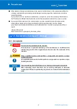
Page 12: ...nces and notifications etc Contact a nearby sales office or agent Sales offices list https www ulvac co jp support_info sales_office 1 2 Acceptance transport storage 1 2 1 Acceptance Do not enter the...

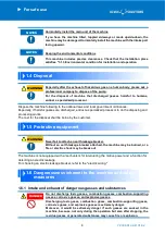
Page 13: ...machine includes precise clearances Check that the storage place satisfies 3 1 2 Environmental condition for storage 1 3 Installation and operation Do not detach the face panel Do not detach the face...

Page 14: ...ost for the disposal shall be borne by the customer 1 5 Protective equipment Never fail to attach an earth leakage breaker Without an earth leakage breaker attached the machine may be burned or a fire...

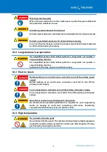
Page 15: ...t or injury 1 6 3 Electric shock Before working on an electric wire connection turn off the primary power supply Before working on an electric wire connection never fail to turn off the primary power...

Page 16: ...f the machine Measure the pressure on the pump exhaust side and if it is 0 03 MPaG 0 3 kg cm2G gauge pressure or more remove the obstacle that blocks the passage of the gas on the exhaust side If the...

Page 17: ...less during operation Operation without load ICF flange type Measured by us Compact and light weight design Excellent operationality Simple operation with a touch panel A dedicated display for vacuum...

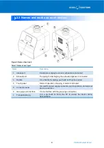
Page 18: ...hausted gasses is connected 3 Handle It is a handle for placing your hand to lift up the product 4 Touch panel Status of operation stopping or alarm is indicated 5 Connector panel It is used for power...

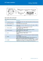
Page 19: ...ector It is a low vacuum area vacuum gauge import connector Supports following G TRAN models SW1 1 SP1 6 D CC It is a capacitance manometer import connector Supports following G TRAN models CCMT D 7 C...

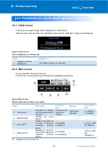
Page 20: ...arted up or stopped by operating the switches Figure 5 Main screen Table 4 Explanation of main screen switch Name Description Turning on light Blinking Turning off light 1 VAC switch Operation for sta...

Page 21: ...s indicated when the P1 is specified for high vacuum P1 Nothing is indicated when NO USE is specified 7 Indication of P2 pressure Output operation value of the device is indicated when the P2 is speci...

Page 22: ...t operation sound 4 Delay timer switch It is used for setting the Rough VAC time Based on the delay timer setting during the Rough VAC the time spent for discharging by FP only can be specified withou...

Page 23: ...cuum Target devices ST2 SH2 only For using in ST2 SH2 single unit mode ST2 SH2 combi For using in ST2 SH2 combination mode SC1 2 ST2 SH2 combi switch 3 SC1 switch 4 NO USE switch When the P1 display s...

Page 24: ...rminal that outputs DC24V and if a wrong connector is chosen the connected device may possibly be damaged therefore carefully check the connection destination By selecting the etc 1 etc 2 on the P1 an...

Page 25: ...ice abnormal signal Normal open 8 Input of analog signal DC0 10V 9 Power supply GND 10 Signal GND 15 Signal GND D IG 1 Input of power supply DC 24V 2 Input of device abnormal signal Normal open 5 Outp...

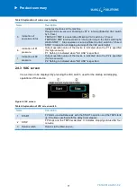
Page 26: ...rge to stop vacuum measurement 3 Return switch Returns to the Main screen 2 4 10 DEG screen It is a screen to be displayed by pressing the DEG switch for operating the degassing of G TRAN probe specif...

Page 27: ...lity is not eliminated the alarm generates again 2 4 12 Numeric key screen It is a ten key to be displayed by pressing the numeric value frame for entering numeric values Name Description 1 0 9 keys E...

Page 28: ...ay take on whole or part of the transportation unpacking and installation Packing We Transportation Instruction from us to a designated contractor Receipt of shipment and unpacking Customer Inspection...

Page 29: ...be kept away from a heat source The machine shall not be tilted for 10 degrees or more 3 1 3 Environmental condition for installation and operation This machine includes precise clearances For install...

Page 30: ...r damage For a wooden frame packing wear leather gloves and use an appropriate tool for disassembly When doing the works the nails or wood pieces that fix the wooden frame may wound the worker s hand...

Page 31: ...the gasket 1 CNSIL connector 1 Jumper pin For Start interlock 1 For CNSIL 3 4pin Instruction manual CD ROM 1 Cautions for safety 1 Table 16 Option article list Name Specification AC code Country Allo...

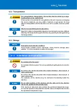
Page 32: ...e on a cart or a pallet and use a pallet truck Wear safety shoes for transportation Never fail to wear safety shoes for transporting the machine Attach a transportation jig for transportation Never fa...

Page 33: ...pump internal pressure raises to 0 03 MPaG or more the pump may be burst Remove the flange cap for piping connection Before the factory shipment a flange cap is attached to the intake port flange sec...

Page 34: ...UTM 70B Introduce N2 gas for the purge gas type with the volumetric flow of 25mL min Start of gas supply After the startup of the auxiliary pump but before the process gas discharge Stop gas supply A...

Page 35: ...lly which may end up in burnout or fire breakout Follow the rules regulations and ordinances Install and operate the machine according to the rules regulations and ordinances Fire Service Laws and ele...

Page 36: ...aching a device that may interfere in the passage of gasses on the exhaust port side such as covering the port This may raise the inner pressure of the machine and may end up in blowout of casing or o...

Page 37: ...e the shipment Remove the transportation jigs before starting up the operation Keep the transportation jigs with care so as not to lose them Figure 16 Removal of transportation jigs 2 Check that conne...

Page 38: ...e time specified in the delay timer elapses TMP ACC is indicated on the operational status display When the startup operation of the TMP completes the VAC switch turns into lighting from blinking TMP...

Page 39: ...ntains an interface capable of forcibly shutting down the operation by inputting signals into CNSIL connector 1 2 pin and 3 4 pin Table 17 External interlock pin assignment Connector PIN No Operation...

Page 40: ...eck the connection destination It is possible to simply display G TRAN output operation value by connecting Ulvac transducer type vacuum gauge G TRAN series to this machine 4 4 1 Setting of G TRAN 1 C...

Page 41: ...ed to CCMT D 3 Press Menu on the Main screen to display the Menu screen 4 Select a G TRAN model to be connected by P1 and P2 on the Menu screen Figure18 Menu screen and G TRAN models on the P1 and P2...

Page 42: ...switch the filament is turned OFF and the pressure measurement is stoppe 7 Changeover of P1 filament If G TRAN SH2 1 is used the filament used for the contact signal between CNSI 5 6 pin can be chang...

Page 43: ...of the connector panel The corresponding connector and display section are as follows Display Connector Device P1 D IG Equipment with ON OFF operation such as filament and discharge such as ionization...

Page 44: ...the P1 and P2 screen etc 1 etc 2 functions Switch Function Work etc 1 P a 10 V b c d P Display Value V Input Voltage DC0 10V A b c d variable etc 2 P V a b 5 Press Return switch to return to the Main...

Page 45: ...sure measurement is stoppe 7 Changeover of P1 filament If G TRAN SH2 1 is used the filament used for the contact signal between CNSI 5 6 pin can be changed over Connector Contact signal Description CN...

Page 46: ...nd kept stored for a long time six months the operation of the machine may be interfered because of moisture absorption or lubrication defect etc If the machine is kept unoperated for a long time entr...

Page 47: ...ation jig End Breakdown of FP Contact a service center End Breakdown of TMP Contact a service center End The exhaust side is covered Check around the exhaust port 3 4 1 Leakage of intake side piping I...

Page 48: ...of the device Display Alarm name State P2 ALARM Abnormality of the device specified in P1 Display Alarm name State TMP ALARM TMP detects an abnormality Cause Responding method Reference Overload on T...

Page 49: ...owing methods Handling after alarm generation Method for resetting alarm After eliminating the cause of alarm reset the alarm and re start the machine In a condition when the characters representing t...

Page 50: ...2 N2 L s 70 He L s 60 H2 L s 49 Backing pump L min 20 Weight kg 17 5 Noise 3 dB A 43 Input power source Single phase AC100 240V 50 60Hz Power capacity W 300 dimension Width mm 318 Length 329 Height IC...

Page 51: ...0012 AI 101 02 7 2 External dimensional drawing Figure 20 External dimensional drawing Inlet flange H D W ICF114 405 329 318 VG65 387 ISO63 K Specification Inlet Operation screen Gas purge port option...

Page 52: ...cement parts Types Component name Recommended replacing period Recommended replacement component for FP Diaphragm 6 000hr Valve 6 000hr Bearing 15 000hr Recommended replacement component for TMP Beari...

Page 53: ......

Page 54: ...son for return usage situation special notes etc Pollutant Check all the boxes apply It is ensured that the product above is not polluted by hazardous materials The product above is polluted by the fo...

Page 55: ......

Reviews: