SECTION 3
6
3. MOUNTING THE ELECTRON BEAM GUN
3.1 Necessary Equipment
(1)
Power supply unit for electron beam gun
ULVAC HPS series electron beam gun power supply unit, such as
HPS-1000F, HPS-1600F, etc.
(2)
Pumping unit for deposition
1 set
(3)
Gun base (SUS 304) for the above
1 set
(4)
High voltage feed-through
2P (dual)
(50 A, 12,000 VDC or more)
* ULCAV BERH-311A (100 A, 12,000 VDC, 1P) is recommended.
(5)
Feed-through for magnet coil
(Current capacity: 5 A, breakdown voltage: 250 VAC or more)
* ULVAC recommends the use of PTS-004 (8P).
(6)
Ground terminal
Fix an M10 bolt to the electron beam gun chamber wall and connect it to the
gun by means of a copper strip.
Outside the chamber, the bolt is connected to the earth cable and ground cable
of the E/B power supply.
* ULVAC recommends the use of ERZ-003.
(7)
Grounding (10 or less)
* See the Electron Beam Gun Power Supply instruction manual.
(8)
Flow switch
* ULVAC Model GTF-A (2 to 20 L/min) can be used.
(9)
Chamber close switch
125 VAC, 0.5 A
(10)
Vacuum interlock switch
125 VAC, 0.5 A
ULVAC Model DTA-001 can be used. Interlocking can be done more
effectively by using the meter relay of the ionization gauge.
(11)
Water feed-through
Inside diameter: 8mm-dia. or more
2P/gun
(12)
Evaporation source shutter mechanism
1 set
(13)
Hearth rotation mechanism
1 set
Two-thirds turn of the hearth drive shaft of the EGL-206M/EGL-406M
moves one crucible.
Summary of Contents for EGL-206M
Page 2: ...EB0007 03e...
Page 3: ...EB0007 03e...
Page 10: ......
Page 13: ...SECTION 1 3 Fig 1 1 Dimensional Drawing for EGL 206M EGL 406M...
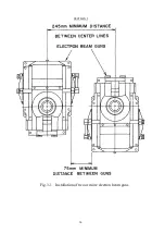
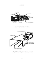
Page 24: ...SECTION 3 14 Fig 3 1 Installation of two or more electron beam guns...
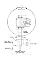
Page 26: ...SECTION 3 16 Fig 3 3 Typical water cooling piping arrangement...
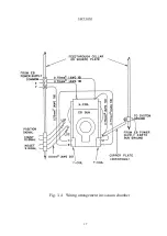
Page 27: ...SECTION 3 17 Fig 3 4 Wiring arrangement in vacuum chamber...
Page 38: ...SECTION 5 28 Fig 5 1 Exploded view of emitter assembly and dimensional drawing for electrode...
Page 42: ...SECTION 5 32 Fig 5 2 Exploded view of EGL 206M EGL 406M...


