SECTION 3
10
in diameter if it exceeds 20 cm. If the cable length is greater than this,
connect a solderless terminal to the end of the cable by welding (do not
solder). If the cable end is connected by compression alone, the connection
will become loose due to heat cycle and trouble may result. A multi-wire
cable can be used by simply clamping the terminal with a terminal cramper.
Filament cables are energized with a high voltage of 10 kVDC in maximum;
so lay cables at least 15 mm away from the ground potential portion.
NOTE
If filament cable is too short, a filament terminal has overstress by thermal
expansion in operation. It may cause deformation of a filament terminal or
causes displacement of a beam former. So recommended length of a filament
cable is more than 30cm.
(6)
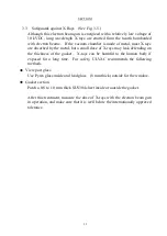
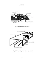
Gun shield (See Fig. 3.2.)
Cover the filament cables with a SUS304 stainless steel cover (0.4 to 1.0
mm). Since the filament cables are energized with a high voltage of 10
kVDC in maximum, keep a spacing of 15 mm or more between the gun shield
and the cable.
Also consider the exhaust conductance so that the vacuum level inside the
shield is not deteriorated due to gas emitted from evaporant.
If the gun shield is not provided, gas particles ionized with the electron beam
will sputter the filament cables and the cables will wear in a short time. It is
also likely that an insulation layer will be formed on the surface of the
filament cable and this may cause abnormal discharge. The ionized particles
will also enter the electron beam path and strike against a part of the emitter
assembly, causing local wear.
NOTE
1.
Worn parts by sputtering of Ionized gas particles need replacement.
2.
A filament cable tends to be sputtered locally. If sputtered part of the cable
become apox.80% compared to new one, please replace it.
Summary of Contents for EGL-206M
Page 2: ...EB0007 03e...
Page 3: ...EB0007 03e...
Page 10: ......
Page 13: ...SECTION 1 3 Fig 1 1 Dimensional Drawing for EGL 206M EGL 406M...
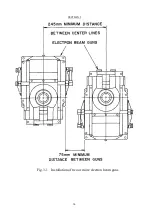
Page 24: ...SECTION 3 14 Fig 3 1 Installation of two or more electron beam guns...
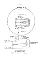
Page 26: ...SECTION 3 16 Fig 3 3 Typical water cooling piping arrangement...
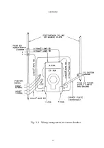
Page 27: ...SECTION 3 17 Fig 3 4 Wiring arrangement in vacuum chamber...
Page 38: ...SECTION 5 28 Fig 5 1 Exploded view of emitter assembly and dimensional drawing for electrode...
Page 42: ...SECTION 5 32 Fig 5 2 Exploded view of EGL 206M EGL 406M...


