SECTION 4
21
4.2 Operation of Electron Beam Gun
Read the power supply for the electron beam gun instruction manual in
conjunction.
(1)
Charge the crucible with evaporant.
If the evaporant is a metal, it is desirable to use a high purity material
that
has been degassed in vacuum. Ideally, the shape of the
evaporant is the
same as that of the crucible, but granular material can also be used. Powered
material should be avoided.
If the evaporant is a compound, hot-pressed, granular, flake or ingot
evaporant is suitable. In any case, use a high quality material that does not
emit much gas.
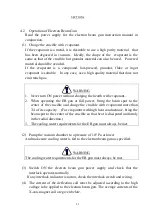
WARNING
1.
Never turn ON power without charging the hearth with evaporant..
2.
When operating the EB gun at full power, bring the beam spot to the
center of the crucible and charge the crucible with evaporatnt more than
3/4 of its capacity. (For evaporant with high heat conductance, bring the
beam spot to the center of the crucible so that heat is dissipated uniformly
in the radial direction.)
3.
The cooling water requirements for the EB gun must always be met.
(2)
Pump the vacuum chamber to a pressure of 10
-3
Pa or lower
And make sure cooling water is fed to the electron beam gun as specified.
WARNING
The cooling water requirements for the EB gun must always be met.
(3)
Switch ON the electron beam gun power supply and check that the
interlock operates normally.
If any interlock indicator is not on, check the interlock switch and wiring.
(4)
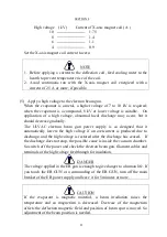
The current of the deflection coil must be adjusted according to the high
voltage to be applied to the electron beam gun. The average currents of the
X-axis magnet coil are given below.
Summary of Contents for EGL-206M
Page 2: ...EB0007 03e...
Page 3: ...EB0007 03e...
Page 10: ......
Page 13: ...SECTION 1 3 Fig 1 1 Dimensional Drawing for EGL 206M EGL 406M...
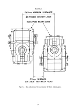
Page 24: ...SECTION 3 14 Fig 3 1 Installation of two or more electron beam guns...
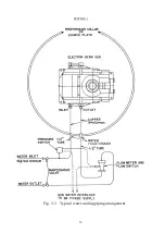
Page 26: ...SECTION 3 16 Fig 3 3 Typical water cooling piping arrangement...
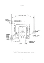
Page 27: ...SECTION 3 17 Fig 3 4 Wiring arrangement in vacuum chamber...
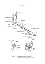
Page 38: ...SECTION 5 28 Fig 5 1 Exploded view of emitter assembly and dimensional drawing for electrode...
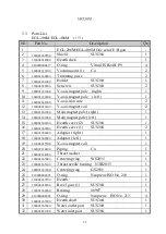
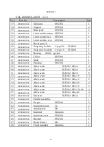
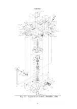
Page 42: ...SECTION 5 32 Fig 5 2 Exploded view of EGL 206M EGL 406M...

