SECTION 4
22
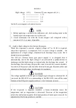
High voltage ( kV ) Current of X-axis magnet coil ( A )
10
1.75
8
1.4
6
1.1
4
0.9
Set the X-axis magnet coil current to zero.
NOTE
1.
Before applying a current to the deflection coil, feed cooling water to the
hearth to prevent temperature rise of the coil.
2.
Avoid continuous run with the X-axis magnet coil energized with a
current of 2.5 A or more, if possible.
(5)
Apply a high voltage to the electron beam gun.
When the evaporant is a metal, a higher voltage of 7 to 10 kV is required;
when the evaporant is a compound, 8 kV or lower voltage is suitable. On
application of a high voltage, abnormal local discharge may occur, but it
should decrease gradually.
The ULVAC electron beam gun power supply is so designed that it
automatically lowers the high voltage if an overcurrent is produced due to
discharge, and the high voltage is restored after the discharge has ceased. If
the discharge does not stop, the possible cause is inside the vacuum chamber.
So switch off the power and check the electron beam gun, filament cables and
terminals of the high voltage feedthrough for insulation.
DANGER
The voltage applied in the EB gun is enough to give danger to a human life. If
you touch the EB GUN or a surrounding of the EB GUN, turn off the main
breaker of the EB power supply and leave it for 5 minutes or more.
CAUTION
If the evaporant is magnetic material, a beam irradiation raises the
temperature and so magnetism is decreased. Decrease of the magnetism
affects the deflection magnetic field and position of beam spot is moved. So
adjustment of the beam position is needed.
Summary of Contents for EGL-206M
Page 2: ...EB0007 03e...
Page 3: ...EB0007 03e...
Page 10: ......
Page 13: ...SECTION 1 3 Fig 1 1 Dimensional Drawing for EGL 206M EGL 406M...
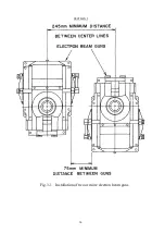
Page 24: ...SECTION 3 14 Fig 3 1 Installation of two or more electron beam guns...
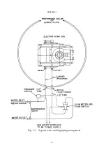
Page 26: ...SECTION 3 16 Fig 3 3 Typical water cooling piping arrangement...
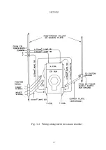
Page 27: ...SECTION 3 17 Fig 3 4 Wiring arrangement in vacuum chamber...
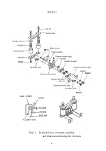
Page 38: ...SECTION 5 28 Fig 5 1 Exploded view of emitter assembly and dimensional drawing for electrode...
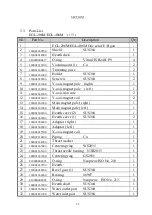
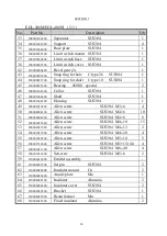
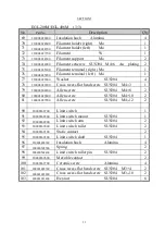
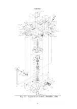
Page 42: ...SECTION 5 32 Fig 5 2 Exploded view of EGL 206M EGL 406M...

