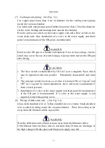
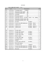
SECTION 5
25
(4)
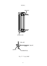
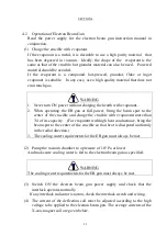
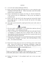
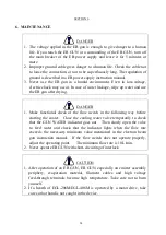
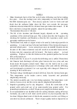
Mounting the emitter assembly
After checking the filament for correct mounting, and filament holders for
absence of foreign matter in between them, insert the emitter assembly to the
unit and fasten the two setscrews securely.
Finally, connect the filament cable.
NOTE
1.
Normally, only the filament needs change. If the component parts of the
emitter assembly are oxidized noticeably, disassemble the assembly and
polish them with a metal brush or the like to remove oxide film.
2.
Dust remaining in the filament or in the component parts of the emitter
assembly causes short-circuiting of the filament. Clean them carefully.
3.
Replace the emitter assembly periodically because ionized evaporated gas
particles strike against a part of the emitter assembly, causing local wear.
4.
The emitter assembly gets hot during operation. Screws tend to become
loose due to temperature cycle and must be firmly tightened. Periodically
retighten them.
5.
Before tightening the setscrews, make sure that the insulator mount is in
intimate contact with the hearth surface. If not, the assembly temperature
will rise during operation, causing an unforeseen trouble.
Summary of Contents for EGL-206M
Page 2: ...EB0007 03e...
Page 3: ...EB0007 03e...
Page 10: ......
Page 13: ...SECTION 1 3 Fig 1 1 Dimensional Drawing for EGL 206M EGL 406M...
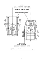
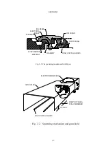
Page 24: ...SECTION 3 14 Fig 3 1 Installation of two or more electron beam guns...
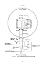
Page 26: ...SECTION 3 16 Fig 3 3 Typical water cooling piping arrangement...
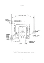
Page 27: ...SECTION 3 17 Fig 3 4 Wiring arrangement in vacuum chamber...
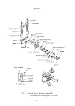
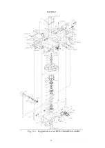
Page 38: ...SECTION 5 28 Fig 5 1 Exploded view of emitter assembly and dimensional drawing for electrode...
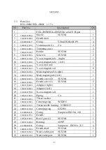
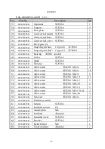
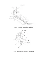
Page 42: ...SECTION 5 32 Fig 5 2 Exploded view of EGL 206M EGL 406M...


