background image


-06-


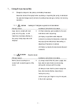
The pump will be damaged if it is subjected to shock it is overturned.   


Always use the pump indoors. 


Pump oil must be put in the pump and the inlet port sealed if storing it unused for a 

long period of time. 


Do not leave the pump unused with moisture inside it. Corrosion of pump 

components is accelerated if it is left in this condition, and the pump may seize and 

no longer rotate. 


0.5 Protective 

Equipment 

A single-phase motor is connected to this pump. 

An overload protection device (automatic-recovery type thermal protector) is built-in 

to the single-phase motor. 

Other protective equipment (e.g. earth leakage breaker) is also recommended to be 

fitted.  


Use the motor only at the rated voltage. Use at a different voltage may result in the 

overload protection not operating correctly, motor burnout, or fire. 

Attention 

Attention 

Attention 

Attention 

Attention 

Summary of Contents for GHD-101A

Page 1: ...Model GHD 101A GHD 101B GHD 101C GHD 101D Read this manual before using the product Keep it in a safe place ready for use as necessary The content of this manual is liable to change without prior not...

Page 2: ...no damage in transit Always read this manual thoroughly before installation operation inspection and maintenance to ensure that the pump retains its performance over the long term and ensure that you...

Page 3: ...te injury or disability to the operator or physical damage if the equipment is used incorrectly There is a possibility of damage to the equipment or problems with operation if the equipment is used in...

Page 4: ...o do this may result in electric chocks or injuries due to the pump suddenly starting Ensure that the equipment is earthed correctly Installation of an earth leakage breaker is recommended Failure to...

Page 5: ...ree of obstacles which may obstruct ventilation Obstructed ventilation may result in fire The pump becomes very hot during operation and it should therefore not be touched either in operation or immed...

Page 6: ...ust therefore be satisfied during storage mounting and operation 1 Temperature and humidity in operation humidity at 7 C 40 C 85 or less RH 2 Maximum height above sea level during storage and operatio...

Page 7: ...s condition and the pump may seize and no longer rotate 0 5 Protective Equipment A single phase motor is connected to this pump An overload protection device automatic recovery type thermal protector...

Page 8: ...the pump safely 1 1 1 Dangers unique to the pump and safety measures 1 1 1 1 Leakage of dangerous gases and substances 1 1 1 2 Electric shock 1 1 1 3 Bursting 2 1 1 4 High temperature 2 1 2 Safety da...

Page 9: ...5 4 8 Attaching the oil mist trap option element 16 4 9 Operation restrictions when attaching the oil mist trap option element 16 4 10 Magnetic coupling 17 5 Pump performance 18 5 1 Ultimate pressure...

Page 10: ...s 7 Fig 5 Wiring drawings 8 Fig 6 Power cord consent Inlet EN60320 1 8 Fig 7 How to attach the fastener and electric cord 9 Fig 8 Fluctuations in the power supply voltage and frequency 11 Fig 9 Exhaus...

Page 11: ...e properly detoxified when dismantling or disposing of hazardous materials Injury due to contact with toxic pump oil in the pump or with hazardous materials adhering to the pump during inspection and...

Page 12: ...es bring a danger of burns if the pump is touched by accident Do not touch the pump while it is in operation Ensure that the pump is stopped and wait until it has cooled before commencing inspection 1...

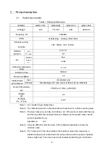
Page 13: ...x 413 5 L x 234 5 H Weight kg 22 Leakage Pa m3 sec 1 10 6 Note 1 G V stands for gas ballast valve Note 2 The ultimate pressure in the above table is that shown on a Pirani vacuum gauge Note 3 The vapo...

Page 14: ...ration and it should therefore not be touched either in operation or immediately after it has stopped Contact with the hot pump may result in burns Select a motor that is appropriate for the power sup...

Page 15: ...h the pump Refer to 0 4 2 surroundings during storage mounting and operation regarding the ambient conditions Fig 2 How to move the sealed rotary vacuum pump The pump weighs 20kg or more and lifting o...

Page 16: ...ist trap is effective when the pump is operated under conditions with a large amount of oil mist when used for a long time under high pressures The pump is not pressure resistant and has an internal p...

Page 17: ...hen the pump is stopped It is not a gas backflow prevention device The backflow prevention device uses the oil pressure inside the pump to return the internal pressure to atmospheric pressure when the...

Page 18: ...fitted Fig 5 Wiring drawings 5 The power cord consent inlet is suitable for EN60320 1 Fig 6 Power cord consent Inlet EN60320 1 6 Insert the power cord into the power cord consent inlet If the power c...

Page 19: ...ectric cord use a fastener It prevents the electric cord from coming out of the consent Select a fastener that fits the shape of the electric cord c How to attach the fastener and electric cord Attach...

Page 20: ...ent point the M4 tap has been provided on the base side of the pump Refer to fig 1 Therefore in case of installing the pump in the housing etc it can also be connected to housing and the pump in the g...

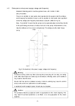
Page 21: ...uch as a rise in temperature The ratings are the rated torque N m Fig 8 Fluctuations in the power supply voltage and frequency Commence wiring work only after removing the power plug Do not carry out...

Page 22: ...n large amounts of water etc are introduced into the pump If the oil is used after moisture has been introduced the lubrication properties of the oil will decrease and the pump parts will rust leading...

Page 23: ...may result in burns The pump gets hot during operation 40 80 C so don t touch the motor or pump body 2 Oil mist comes out of the exhaust when the pump is operated at high pressures Either attach an oi...

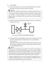
Page 24: ...tee to do this 100 In the case that the internal pressure is not returned to atmospheric pressure when the pump is stopped approximately 400 ml of oil will enter the vacuum chamber in a short time Als...

Page 25: ...re the higher the gas ballast effect So before introducing condensed gases to the pump open the gas ballast valve and operate the pump for approximately 20 minutes When the temperature has risen to ab...

Page 26: ...T 100A OMT 200A OMI 100 or OMI 200 oil mist trap to the exhaust section instead of the standard exhaust port Attaching one of these oil mist tarps will prevent the oil mist from being exhausted and al...

Page 27: ...reassembling it When starting the pump when the ambient temperature is low and the pump oil viscosity is high When starting the pump when there is a problem pump lock etc inside the pump In these case...

Page 28: ...il become gas again and increase the ultimate pressure Deterioration of the pump oil 3 Vacuum leaks in the vacuum path that lead to gas being introduced increase the ultimate pressure 5 2 Exhaust velo...

Page 29: ...19 Fig 9 Exhaust velocity curve...

Page 30: ...tion Failure to do so may result in injury 2 The pump is hot immediately after use Wait for it to cool before inspecting Failure to do so may result in burns 1 Inspecting the electric cord and wiring...

Page 31: ...t there are no loose nuts and bolts etc 7 Oil mist trap inspection When using an oil mist trap instead of the standard exhaust port pay attention to whether the filter inside the oil mist trap is clog...

Page 32: ...turer for further clarification Surface temperature Check that the surface temperature is normal 50 C or more above room temperature is abnormal Check for causes of overload Contact the manufacturer f...

Page 33: ...caused by contamination due to intake gases but is also caused by normal pump operation over time We recommend that you periodically change the oil as shown in Table 5 If the pump has been used to exh...

Page 34: ...unt decreases to where it cannot be seen on the oil level gauge the ultimate pressure will increase and the exhaust noise may not stop If the oil amount is more than the maximum oil level oil drops ma...

Page 35: ...ctive gas was introduced and caused reactive products to accumulate inside the pump while it was stopped 9 Disassemble and repair clean the inside of the pump and remove the reactive products 6 2 10 O...

Page 36: ...n cover etc 5 Disassemble and repair Clean the oil holes 6 2 6 Other pump internal parts have broken 6 Disassemble and repair replace the broken parts 6 2 Pump surface is abnormally hot room temperatu...

Page 37: ...by your local authority 1 Engage the services of a specialist contractor for disposal if the pump has been used to exhaust toxic or dangerous gases The pump body and pump oil become toxic 2 Dispose o...

Page 38: ...0 O ring _S 6 3 51 O ring _S 7 1 52 O ring _S 16 1 53 O ring _S 20 1 54 O ring _S 32 1 55 O ring _S 53 1 56 O ring _S 71 2 57 O ring _P 5 1 58 O ring _P 8 1 59 O ring _P 9 2 60 O ring _P 12 1 61 O rin...

Page 39: ...29 8 2 Disassembly drawings Fig 11 GHD 101 Sealed rotary vacuum pump disassembly drawings...

Page 40: ...rformance details maintenance inspection d Malfunctions caused by modification or repair that is carried out by a party other than the manufacturer or by a service company not approved by the manufact...

Page 41: ...may require notification under the Occupational Safety and Health Act 2 Usage Operation hours day months year Continuous operation Intermittent operation Details of use 3 Malfunction details Abnormal...

Reviews: