16
smaller than the setpoint value, and the condition is maintained continuously for more than 0.5 second.
When the setpoint output is turned ON, the green LED displaying the setpoint output action on the front
panel lights up.
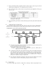
Use the setpoint output load within the following range.
Rated voltage
24 V DC
Maximum rated current
50mA
*The setpoint output is not turned ON for about three seconds after power is turned ON regardless of
the measurement value.
6.5.
27B
Adjusting the Recorder (Analog) Output
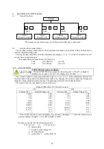
The recorder has been factory adjusted. If the displayed value and the output value differ from each
other, adjust the recorder output according to the following procedure.
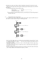
Data is set with the [▲] switch, and ± of the data can be selected with the [
▶
] switch. If the “?” on the
SV indicator in the figure above d
isplays ”_”, data value will be decremented with the [▲] switch and
incremented if it is blank.
The recorder output offset is variable from –
1500 to +1500 with the [▲] switch an the output voltage
at this time is –0.8 to +1.8 V.
The output adjustment range of span is variable from –2500 to +1500, and the output voltage range at
this time is +7.0 to +11.8 V.
However, the numerical value displayed in this mode is not directly related to the actual recorder output
value. So make adjustment while measuring the output by a voltmeter.
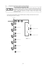
Pressure
+
SET
X X X X
Output voltage ZERO adjust
?oL
SET Set
DATA cancel
X X X X
?oH
▲
Output voltage SPAN adjust
SET Set
DATA cancel
Pressure


