RF POWER SUPPLY and MATCHINGBOX
2. Overview
3
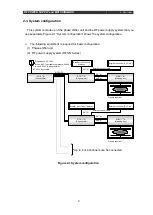
2-3. System configuration
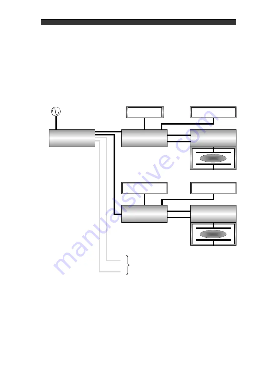
This system is made up of the phase shifter unit and the RF power supply system that you
use separately. Figure 2-1
“System configuration” shows the system configuration.
The following equipment is required for basic configuration.
(1) Phase shifter unit
(2) RF power supply system (RFS-N Series)
Figure 2-1 System configuration
Plasma chamber
Single-phase AC 100 V
(When a AC input cable compliant with 200 V
is used, 200 V is also possible)
AC 100 V input cable
RFS-OSC
PHS-**N
(Phase shifter)
RFS-****N
(RF generator)
MBX-****N
(Matching box)
Breaker (short circuit
breaker)
External controller (PLC, etc.)
AC**-N
External control cable
RF**-N
AMC-N
RFS-****N
(RF generator)
Breaker (short circuit breaker)
MBX-****N
(Matching box)
External controller (PLC, etc.)
AC**-N
External control cable
RF**-N
AMC-N
Up to 4 or 8 channels can be connected
Plasma chamber
Summary of Contents for PHS-04N
Page 2: ......
Page 17: ...RF POWER SUPPLY and MATCHINGBOX 3 Preparation 9 Figure 3 2 System wiring example...
Page 28: ...RF POWER SUPPLY and MATCHINGBOX 7 Reference materials 20 Figure 7 1 PHS 04N External diagram...
Page 29: ...RF POWER SUPPLY and MATCHINGBOX 7 Reference materials 21 Figure 7 2 PHS 08N External diagram...


