


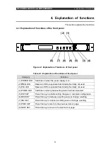
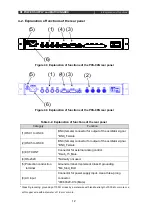


RF POWER SUPPLY and MATCHINGBOX
3. Preparation
7
Danger:
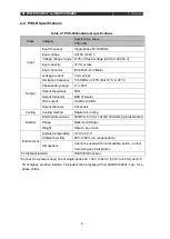
To prevent electric shock, always implement a protective ground before
switching on the power of this equipment. The power supply cord included with
this equipment is a three-prong cord with ground wire. Therefore, use a
three-prong outlet with a protective ground terminal. Furthermore, when a
three-prong to two-prong conversion adapter is to be used, connect the ground
wire of the conversion adapter reliably to the protective ground terminal. If an
extension cord without a protective ground wire is used, the protection function
is not available. When you will use a two-prong cord, always implement a Class
D grounding of the ground terminal on the main unit.
3-2-1. Attachment method and rack manufacturing
The configuration of PHS enables attachment to a full rack. When machining rack
attachment holes, refer to the included exterior diagram.
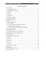
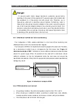
The front panel of PHS is not constructed to bare the weight of the main unit. Therefore,
set a construction in which force is not applied to the front panel. See "
Figure 3-1
Attachment example of PHS
". Furthermore, ensure sufficient clearance to allow air intake
around the power supply. When the product will be used with a rackmount, ensure
sufficient ventilation so that the temperature inside the rack does not exceed the
specification temperature. If the product is operated at a temperature outside specifications,
damage may result.
Figure 3-1 Attachment example of PHS
3-2-2. PHS installation environment
At operating conditions, the ambient temperature must be from 10°C to 40°C.
When choosing an installation location, avoid direct sunlight, heat, dust, vibration,
humidity and other similar conditions, and choose a location with good ventilation.
The atmosphere must not include corrosive gas.
PHS
ラ
ッ
ク
ラ
ッ
ク
↑下から支える構造にする
パネルに力がかからないような構造
ししてください。
Construct so that force is not
applied to the panel.
Rack
Rack
↑ Set a structure to support from below
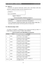
Summary of Contents for PHS-04N
Page 2: ......
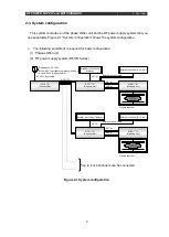
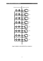
Page 17: ...RF POWER SUPPLY and MATCHINGBOX 3 Preparation 9 Figure 3 2 System wiring example...
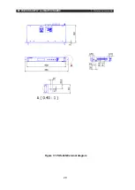
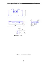
Page 28: ...RF POWER SUPPLY and MATCHINGBOX 7 Reference materials 20 Figure 7 1 PHS 04N External diagram...
Page 29: ...RF POWER SUPPLY and MATCHINGBOX 7 Reference materials 21 Figure 7 2 PHS 08N External diagram...


