RF POWER SUPPLY and MATCHINGBOX
3. Preparation
10
* The customer must separately prepare the RF power supply system unit to be used.
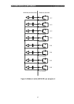
* Up to 8 RF power-supply units can be used simultaneously with the PHS. When fewer than
8 units are to be used, connection to the BNC connector of an unused oscillation signal
output section is not necessary.
* Use a coaxial cable for oscillation signal output (OSC-RFS cable) of up to 24 m. When a
cable longer than 24 m is used, equipment may not operate normally due to attenuation by
the cable.
* Use the equipment after changing the setting to enable the external oscillation signal in the
settings of the RF power-supply to be used.
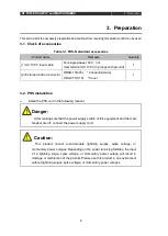
Table 3-2 Cable list
Product name
Remarks
Quantity
(1) AC 100 V input cable
For single phase AC 100 V, 3 m
1
User terminal AC 100 V (3 prongs with ground)
(2) RFS-OSC cable
Coaxial cable 3D-2V (24 m or less)
Number of
channels used
* When the RFS-OSC cable (3D-2V) is laid, keep it as far as possible from the chamber, RF
output coaxial cable, and matching box and do not bundle it with other cables. If the cable is
laid in direct contact, high frequencies will be superimposed on the cable, which may cause
a burnout.
Summary of Contents for PHS-04N
Page 2: ......
Page 17: ...RF POWER SUPPLY and MATCHINGBOX 3 Preparation 9 Figure 3 2 System wiring example...
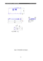
Page 28: ...RF POWER SUPPLY and MATCHINGBOX 7 Reference materials 20 Figure 7 1 PHS 04N External diagram...
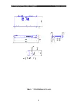
Page 29: ...RF POWER SUPPLY and MATCHINGBOX 7 Reference materials 21 Figure 7 2 PHS 08N External diagram...

