


RF POWER SUPPLY and MATCHINGBOX
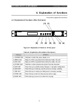
4. Explanation of functions
12
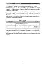
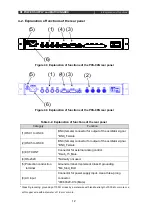
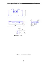
4-2. Explanation of functions of the rear panel
Table 4-2. Explanation of functions of the rear panel
Category
Function
(1) OSC1 to OSC4
BNC (female) connector for output of the oscillator signal.
*BNC_Female
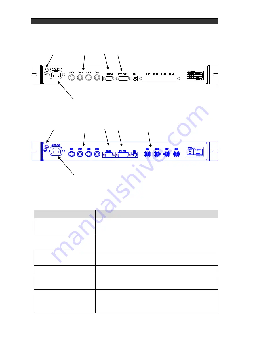
(2) OSC5 to OSC8
BNC (female) connector for output of the oscillator signal.
*BNC_Female
(3) EXT.CONT
Connector for external analog control.
*Dsub_15_Male
(4) RS-232C
*Normally not used.
(5) Protection conduction
terminal
Ground terminal. Implement Class D grounding.
*M4_Stud_Bolt
(6) AC input
Connector for power supply input. Use a three-prong
connector.
*IEC60320-C14 (Male)
*
Class D grounding: grounding of 100 Ω or less by a metal wire with tensile strength of 0.39 kN or more or a
soft copper wire with a diameter of 1.6 mm or more.
(1)
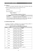
Figure 4-3 Explanation of functions of the PHS-04N rear panel
(3)
(4)
(5)
Figure 4-3 Explanation of functions of the PHS-08N rear panel
(6)
(1)
(2)
(3)
(4)
(5)
(6)
Summary of Contents for PHS-04N
Page 2: ......
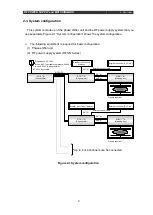
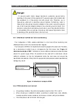
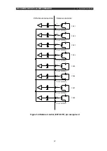
Page 17: ...RF POWER SUPPLY and MATCHINGBOX 3 Preparation 9 Figure 3 2 System wiring example...
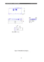
Page 28: ...RF POWER SUPPLY and MATCHINGBOX 7 Reference materials 20 Figure 7 1 PHS 04N External diagram...
Page 29: ...RF POWER SUPPLY and MATCHINGBOX 7 Reference materials 21 Figure 7 2 PHS 08N External diagram...


