RF POWER SUPPLY and MATCHINGBOX
5. Operation methods
13
5. Operation methods
This section explains the operation methods.
5-1. Switching on the power supply
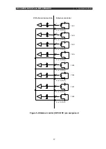
If the POWER switch is set to ON, the following screen appears, and settings can be
configured. If the screen appears after the POWER switch is set to ON, output starts
automatically in accordance with the setting values of the screen display. (*Because output is
not stable until the charging of the electrolytic condenser is complete just after the POWER
switch is set to ON, wait 5 seconds, and then carry out the necessary operations.)
To change the parameters, press the ENT key to make the display items flash.
Next, press the NEXT key to select the item to be configured.
Next, press the INC or DEC key to change the parameter.
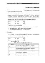
5-2. Screen 1
At Screen 1, the phase settings for the standard waveform can be configured from 0.0°
to 359.9° for each channel from P01(CH1) to P04(CH04).
Table 5-1 Explanation of functions of Screen 1
Category
Function
P01
Adjust the phase of the waveform output from OSC1.
Configurable from 0.0° to 359.9°.
P02
Adjust the phase of the waveform output from OSC2.
Configurable from 0.0° to 359.9°.
P03
Adjust the phase of the waveform output from OSC3.
Configurable from 0.0° to 359.9°.
P04
Adjust the phase of the waveform output from OSC4.
Configurable from 0.0° to 359.9°.
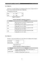
P01=
0.0
P02=
0.0
P03=
0.0
P04=
0.0
Figure 5-1 Screen 1 (default screen)
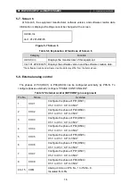
P01=
0.0
P02=
0.0
P03=
0.0
P04=
0.0
Figure 5-2 Screen 1
Summary of Contents for PHS-04N
Page 2: ......
Page 17: ...RF POWER SUPPLY and MATCHINGBOX 3 Preparation 9 Figure 3 2 System wiring example...
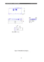
Page 28: ...RF POWER SUPPLY and MATCHINGBOX 7 Reference materials 20 Figure 7 1 PHS 04N External diagram...
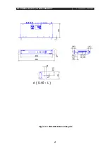
Page 29: ...RF POWER SUPPLY and MATCHINGBOX 7 Reference materials 21 Figure 7 2 PHS 08N External diagram...

