RF POWER SUPPLY and MATCHINGBOX
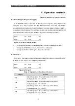
5. Operation methods
14
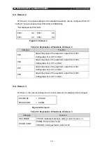
5-3. Screen 2
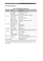
At Screen 2, the phase settings for the standard waveform can be configured from 0.0°
to 359.9° for each channel from P05(CH5) to P08(CH08).
*Not displayed by PHS-04N.
Table 5-2 Explanation of functions of Screen 2
Category
Function
P05
Adjust the phase of the waveform output from OSC5.
Configurable from 0.0° to 359.9°.
P06
Adjust the phase of the waveform output from OSC6.
Configurable from 0.0° to 359.9°.
P07
Adjust the phase of the waveform output from OSC7.
Configurable from 0.0° to 359.9°.
P08
Adjust the phase of the waveform output from OSC8.
Configurable from 0.0° to 359.9°.
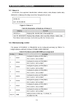
5-4. Screen 3
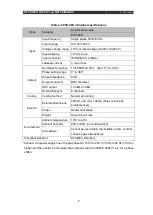
At Screen 3, the current setting state of control mode can be displayed and changed.
Table 5-3 Explanation of functions of Screen 3
Category
Function
OSC MODE
PHASE: indicates that phase setting control mode is on.
PHASE CONT
PANEL: Panel control mode.
ANALOG: Analog external control mode.
P05=
0.0
P06=
0.0
P07=
0.0
P08=
0.0
Figure 5-3 Screen 2
OSC MODE
= PHASE
PHASE CONT
= PANEL
Figure 5-4 Screen 3
Summary of Contents for PHS-04N
Page 2: ......
Page 17: ...RF POWER SUPPLY and MATCHINGBOX 3 Preparation 9 Figure 3 2 System wiring example...
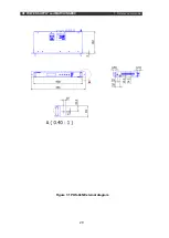
Page 28: ...RF POWER SUPPLY and MATCHINGBOX 7 Reference materials 20 Figure 7 1 PHS 04N External diagram...
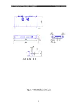
Page 29: ...RF POWER SUPPLY and MATCHINGBOX 7 Reference materials 21 Figure 7 2 PHS 08N External diagram...

