background image

RF POWER SUPPLY and MATCHINGBOX


6.  Maintenance 


18 

6.  Maintenance 

This section explains the maintenance necessary to use this product for many years. 

If maintenance is neglected, the product will deteriorate more quickly and result in breakdown. 

Perform maintenance after reading this section carefully. 


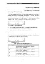
6-1. Maintenance and inspection 


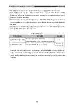
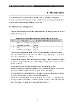
We recommend performing an overhaul at the usage intervals listed below so that you can 

use PHS-N for many years. 


Table 6- Parts of PHS-04N recommended for periodic replacement 

No. 

Part name 

Recommended exchange usage interval 

Organic EL display section  4 years 

Electrolytic condenser 

4 years 

Fuse 

4 years 

Switching power supply 

4 years 

* The recommended exchange usage intervals do not guarantee the lifetime of the parts. 

* The  speed  of  deterioration  of  these  parts  differs  greatly  depending  on  your  usage 

frequency and conditions of the device. 

* In particular, the lifetime of power semiconductors changes by usage methods. High usage 

environment  temperatures,  frequent  on/off  cycling,  and  operation  near  rated  values 

shorten the lifetime. 

* Higher usage environment temperatures further shorten the lifetime of parts. 

* Machine operation parts (such as contactors) have a lifetime prescribed by the number of 

operations. Therefore, lifetime is shortened by the number of operations. 

* When equipment has been stored while off, internal elements may deteriorate in a shorter 

time than the recommended periodic exchange intervals above. 

* Always  have  ULVAC  perform  the  overhaul.  When  the  customer  or  a  third-party  has 

exchanged parts without ULVAC’s permission, ULVAC will charge a fee both during and 

after the warranty term based on the free-repair regulations (P.V). 


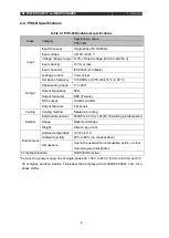
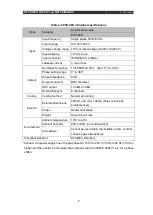
Summary of Contents for PHS-04N

Page 1: ...anual Phase shifter MODEL Phase shifter PHS 04N PHS 08N 4th Edition July 01 2023 ULVAC Inc Please be sure to read this manual before using this product In addition store this manual with care so that...

Page 2: ......

Page 3: ...this manual Please understand them well before use of the product Place this instruction manual near this product and store it safely If the product is moved to a different installation location alway...

Page 4: ...n and maintenance Always carefully read and fully understand the details of operation inspection and maintenance before running this product 3 Safety warnings and precautions are clearly specified in...

Page 5: ...nores this safety section may cause minor injury to personnel damage equipment or make adjustments necessary Note There is no direct danger but the content is intended to inform you about operational...

Page 6: ...with the product If you notice a problem verify the symptoms and breakdown condition To prevent loss due to misunderstanding or misrecognition and allow repairs to be completed promptly please try to...

Page 7: ...war 3 Malfunction or failure caused by inattention during handling or mistaken usage 4 A system modified disassembled or repaired without ULVAC s approval When it is confirmed that the sheet metal of...

Page 8: ...ethod and rack manufacturing 7 3 2 2 PHS installation environment 7 3 2 3 Storage environment and transportation conditions 8 3 5 Connection of cables 8 4 Explanation of functions 11 4 1 Explanation o...

Page 9: ...es Note Keep warning labels clean and legible Use a cloth and water to clean warning labels Do not use gasoline organic solvent or other similar items If a label has been damaged lost or become illegi...

Page 10: ...nd other plasma generation power supplies This system can change arbitrarily the phase of output of each power supply for multiple units of RF power supply running at 13 56 MHz 2 2 Features This syste...

Page 11: ...system RFS N Series Figure 2 1 System configuration Plasma chamber Single phase AC 100 V When a AC input cable compliant with 200 V is used 200 V is also possible AC 100 V input cable RFS OSC PHS N Ph...

Page 12: ...Output impedance 50 Output connector BNC Female OSC output 10 dBm 3 dBm Output channels 4 channels Cooling Cooling method Natural air cooling Exterior External dimensions 480 W x 49 H x 192 D Excludi...

Page 13: ...nce 50 Output connector BNC Female OSC output 10 dBm 3 dBm Output channels 8 channels Cooling Cooling method Natural air cooling Exterior External dimensions 480 W x 49 H x 192 D Does not include prot...

Page 14: ...nector male HDA CTH1 10 Cover 1 3 2 PHS installation Install the PHS unit in the following manner Danger After making sure that the power supply switch of this equipment and the main breaker are off c...

Page 15: ...chment holes refer to the included exterior diagram The front panel of PHS is not constructed to bare the weight of the main unit Therefore set a construction in which force is not applied to the fron...

Page 16: ...tions When this product will be transported or stored in a warehouse the ambient temperature must be from 25 C to 55 C the humidity must be 80 or less there must be no condensation and there must be n...

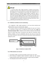
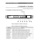
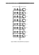
Page 17: ...RF POWER SUPPLY and MATCHINGBOX 3 Preparation 9 Figure 3 2 System wiring example...

Page 18: ...ormally due to attenuation by the cable Use the equipment after changing the setting to enable the external oscillation signal in the settings of the RF power supply to be used Table 3 2 Cable list Pr...

Page 19: ...Reserve LED for expanded functionality Normally not used 3 PLS LED Reserve LED for expanded functionality Normally not used 4 PHASE LED Switches on when phase setting mode has been selected 5 ENT KEY...

Page 20: ...nnector for external analog control Dsub_15_Male 4 RS 232C Normally not used 5 Protection conduction terminal Ground terminal Implement Class D grounding M4_Stud_Bolt 6 AC input Connector for power su...

Page 21: ...key to make the display items flash Next press the NEXT key to select the item to be configured Next press the INC or DEC key to change the parameter 5 2 Screen 1 At Screen 1 the phase settings for th...

Page 22: ...utput from OSC6 Configurable from 0 0 to 359 9 P07 Adjust the phase of the waveform output from OSC7 Configurable from 0 0 to 359 9 P08 Adjust the phase of the waveform output from OSC8 Configurable f...

Page 23: ...566000 Hz Output is stopped temporarily during a change SERIAL Normally not used 5 6 Screen 5 At Screen 5 the equipment name model and serial number information are displayed Settings cannot be change...

Page 24: ...igured externally by PHS N To configure phases externally configure PHASE CONT ANALOG Table 5 7 External control EXT CONT pin assignment Pin No Name Overview 1 CH01 Configure the phase of P01 OSC1 0 5...

Page 25: ...17 PHS N internal section External controller Figure 5 8 External control EXT CONT pin assignment 1 9 to 15 COM CH01 2 CH02 3 CH03 4 CH04 5 CH05 6 CH06 7 CH07 8 CH08 9 to 15 COM 9 to 15 COM 9 to 15 C...

Page 26: ...time of the parts The speed of deterioration of these parts differs greatly depending on your usage frequency and conditions of the device In particular the lifetime of power semiconductors changes by...

Page 27: ...RF POWER SUPPLY and MATCHINGBOX 7 Reference materials 19 7 Reference materials The following materials are appended PHS 04N Exterior diagram PHS 08N Exterior diagram...

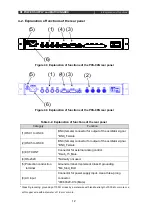
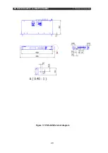
Page 28: ...RF POWER SUPPLY and MATCHINGBOX 7 Reference materials 20 Figure 7 1 PHS 04N External diagram...

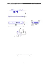
Page 29: ...RF POWER SUPPLY and MATCHINGBOX 7 Reference materials 21 Figure 7 2 PHS 08N External diagram...

Reviews: