YK11-0016-DI-002-08
x
0.4 Types and Descriptions of Warning Labels Displayed on This Machine and
Displayed Positions
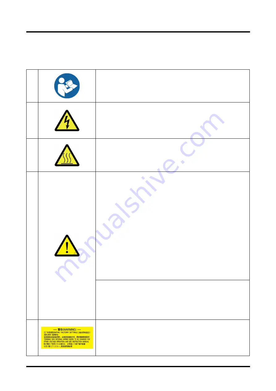
Warning labels are attached on the warning locations in this system.
Be sure to check them before starting operation of the Pump.
1
Before use, read through the instruction manual and fully
understand its contents.
2
・
You may get an electric shock in the area around a portion
with this warning label. Before maintenance or wiring, be sure
to turn off the primary power supply.
・
Be sure to close the lid of the terminal box before operating
this unit. Never open it during operation.
3
During operation or for a while after operation stops, do not
touch the unit as each portion is at a very high temperature. -
If a human body touches the unit, it may get burned.
4
・
This product is not made as the withstand pressure
structure. Ensured pressure value of the Pump shall be
0.03MPaG (0.3kg/cm2G) (Gauge pressure).
・
Do not run the Pump on blocking the Exhaust outlet or
putting any device that might hamper gas passage onto the
outlet. There is a risk that the pressure inside the vacuum
pump rises up to cause break the casing or Oil level gauge
resulting in overload of the motor.
・
Following gases cannot be evacuated because these gases
may cause the
pump inner pressure to increase due to internal combustion.
1) explosive gas
2) flammable gas
3) gas which increases the susceptibility of substances to
burn.
Long term storage of the Vacuum pump without operation
might possibly cause trouble in operation caused by rust if
you kept the Pump long time without operating it, ask a closest
Service Center for the check.
Indoor Use Only
Mount at least 100mm from side walls.
5
Before wiring, please confirm the power-supply voltage you
use.
Please confirm the power-supply voltage you'll use and
change crossline in the terminal box.
Refer to “3.5 Electrical Connection”.
Summary of Contents for PMB100D
Page 2: ......
Page 3: ...Declaration of Conformity...
Page 39: ...YK11 0016 DI 002 08 12 2 4 Dimensional drawing Fig 11 Dimensional drawing PMB100D...
Page 40: ...YK11 0016 DI 002 08 13 Fig 12 Dimensional drawing PMB300D...
Page 41: ...YK11 0016 DI 002 08 14 Fig 13 Dimensional drawing PMB600D...
Page 42: ...YK11 0016 DI 002 08 15 Fig 14 Dimensional drawing PMB1200D...
Page 43: ...YK11 0016 DI 002 08 16 Fig 15 Dimensional drawing PMB2400D...
Page 62: ...YK11 0016 DI 002 08 35...
Page 65: ...YK11 0016 DI 002 08 38...
Page 72: ...YK11 0016 DI 002 08 45...
Page 84: ...YK11 0016 DI 002 08 57 Fig 28 PMB300D Optional attachment figure...
Page 85: ...YK11 0016 DI 002 08 58 Fig 29 PMB600D Optional attachment figure...
Page 86: ...YK11 0016 DI 002 08 59 Fig 30 PMB1200D Optional attachment figure...
Page 89: ...YK11 0016 DI 002 08 62 Fig 33 Dimensional drawing PMB2400D Horizontal exhaust model...
Page 99: ...YK11 0016 DI 002 08 72...
Page 105: ...YK11 0016 DI 002 08 78...
Page 119: ......


