YK11-0016-DI-002-08
31
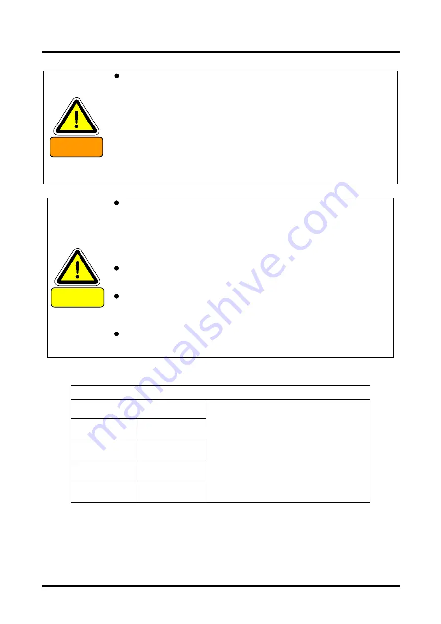
WARNING
If the pipe connected to the outlet had a small diameter or attached
foreign substance inside, it might raise the pressure inside the pipe
and impair the pump operation. A caution shall be required. Mounting
a pressure gauge on the exhaust side of the auxiliary pump, when
the exhaust port pressure 0.03MPaG (0.3 kg / cm2 G) become (gauge
pressure) or more, please provided an interlock which the auxiliary
pump and the pump is stopped . In a state in which the auxiliary pump
is stopped, and to operate the pump, it will be the cause of the
internal pressure of the rising pump damage.
There is a risk that the pressure inside the Vacuum pump rises up to
cause break or oil leak of the casing or Oil level gauge resulting in
overload of the motor.
CAUTION
Wash sufficiently inside the Vacuum chamber, pipes, Vacuum valve
and so on to connect them to the Pump. If dirty unit were connected,
it would cause a trouble such like raise the ultimate pressure or
extend the depression time to the specified pressure. Wear a pair of
gloves to touch any vacuum section. Do not touch with the bare
hand.
Pay attention not to give damage to the Flange sheet face, Gasket
slot or gasket itself.
Use a pipe having bellows between the backing pump and outlet of
the Mechanical Booster Pump so as to avoid any direct load to the
Pump flange.
Do not connect directly the backing pump inlet with the outlet of the
Mechanical Booster Pump.
Use the flange for connection between the pump Outlet and the piping.
MODEL
Flange at the pipe
PMB100D
VG50
JIS B 2290:1998
Vacuum technology-Flange dimensions;
Attachment book (Reference)
Flange dimensions for maintenance
PMB300D
VG80
PMB600D
VG80
PMB1200D
VG80
PMB2400D
VG200
Summary of Contents for PMB100D
Page 2: ......
Page 3: ...Declaration of Conformity...
Page 39: ...YK11 0016 DI 002 08 12 2 4 Dimensional drawing Fig 11 Dimensional drawing PMB100D...
Page 40: ...YK11 0016 DI 002 08 13 Fig 12 Dimensional drawing PMB300D...
Page 41: ...YK11 0016 DI 002 08 14 Fig 13 Dimensional drawing PMB600D...
Page 42: ...YK11 0016 DI 002 08 15 Fig 14 Dimensional drawing PMB1200D...
Page 43: ...YK11 0016 DI 002 08 16 Fig 15 Dimensional drawing PMB2400D...
Page 62: ...YK11 0016 DI 002 08 35...
Page 65: ...YK11 0016 DI 002 08 38...
Page 72: ...YK11 0016 DI 002 08 45...
Page 84: ...YK11 0016 DI 002 08 57 Fig 28 PMB300D Optional attachment figure...
Page 85: ...YK11 0016 DI 002 08 58 Fig 29 PMB600D Optional attachment figure...
Page 86: ...YK11 0016 DI 002 08 59 Fig 30 PMB1200D Optional attachment figure...
Page 89: ...YK11 0016 DI 002 08 62 Fig 33 Dimensional drawing PMB2400D Horizontal exhaust model...
Page 99: ...YK11 0016 DI 002 08 72...
Page 105: ...YK11 0016 DI 002 08 78...
Page 119: ......


