background image


36


SECTION 7


GAS PURGE


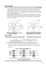
This turbo molecular pump incorporates a gas purge port (Fig. 2-1 (2)). This turbo molecular   

pump need to flow the purge gas for protection of the bearings, when it evacuates a lot of   

corrosive gas. The proper purge gas flow rate is between 20 and 30 mL/min. 


Joint 

Orifice size 

KF10

Dust cap


φ0.5

mm 


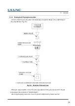
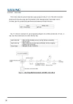
Fig. 7-1 shows an example of a gas purge piping diagram. Use a filter element size of 5 

μ

m, or   

less. Use flow control valve to control the flow rate. 


Gas feed start 

After starting backing vacuum pump; before evacuating 

process gas 

Gas feed stop 

After 

exhausting process gas sufficiently; before stopping 

backing vacuum pump 

Type of gas 

Nitrogen (Purity > 99.99 %) 


Fig. 7-1


Gas Purge Method (adaptor with 

Φ0.5 

mm orifice)


Summary of Contents for UTM-MS Series

Page 1: ...263 13238W INSTRUCTION MANUAL Turbo Molecular Pump UTM MS Series Model UTM300A MS UTM400A MS ULVAC KIKO Inc Before using this product be sure to read this operation manual Keep this manual with care...

Page 2: ...No Text...

Page 3: ...ULVAC KIKO Inc Please refrain from reproducing or copying part or all of this document without permission from ULVAC KIKO In an effort to improve the product this document may be revised in the future...

Page 4: ...se of this product Turbo molecular pump repair and or controller repair can be very hazardous Only trained technicians who are authorized by ULVAC KIKO may do service of products Neither overhaul nor...

Page 5: ...turbo molecular pump is installed to host equipment Do not remove or do maintenance the turbo molecular pump before safety has been confirmed Improper turbo molecular pump use may be hazardous to ope...

Page 6: ...aces 1 Place where the pump is inevitably exposed to significant vibration and impact 2 Unstable place 3 Place where the pump is inevitably exposed to magnetic field and radioactive ray The pump prope...

Page 7: ...4 Do not operate any equipment i e drill motor welding machine etc that produces electro magnetic pollution noise etc in the immediate proximity of an operating turbo molecular pumping system pump co...

Page 8: ...atastrophe if the pump is fixed by insufficient method Fix the pump to host equipment according to Section 5 1 2 Installation of the Pump 3 SECURITY Seal This label certificates that the product was m...

Page 9: ...vii Introduction Location of Label...

Page 10: ...cal cables to be in tension or to have very tight bending radii 3 Unbend the turbo molecular pump cable not to make any kink during connection Part Replacement The lifetime of parts are specified as b...

Page 11: ...iodically because of the cooling fan collecting dust debris etc ULVAC KIKO recommends removal of the cooling fan for all methods of cleaning compressed air etc to prevent the particles cleaning debris...

Page 12: ...x No Text...

Page 13: ...tion of Label vi Location of Label vii Installation Precautions viii Part Replacement viii Air Cooled Turbo Molecular Pump ix Table of contents xi Section 1 OUTLINE AND DESCRIPTIONS 1 1 Outline 2 1 2...

Page 14: ...Direction 20 5 1 2 Installation of the Pump 21 5 1 3 Example of Piping Connection 25 5 1 4 Center of Gravity of the Pump 26 5 2 Connection of the Pump to the controller 27 5 3 Interlock for Vacuum Sy...

Page 15: ...ded Maintenance Intervals 38 8 2 Turbo Molecular Pump Decontamination 39 8 3 Touch down Bearing Replacement 39 8 4 Check of the Rotor Blades 39 8 5 Turbo Molecular Pump Return Request 40 Section 9 TRO...

Page 16: ...xiv No Text...

Page 17: ...1 1 Outline 1 2 Descriptions 1 2 1 Outside Drawing 1 2 2 Standard Accessories OUTLINE AND DESCRIPTIONS...

Page 18: ...ts Industrial equipments R D applications The other ultra high vacuum applications The turbo molecular pump one standard set consists of the following items Pump Unit 1 pc Controller 1 pc Control Cabl...

Page 19: ...Descriptions 1 2 1 Outside Drawing 1 2 1 1 Outside Drawing of UTM300A MS series Inlet flange A B C D E n d F H VG100 272 197 142 185 160 8 12 220 12 ICF152 279 204 149 152 130 3 16 8 4 227 20 Fig 1 1...

Page 20: ...4 SECTION 1 OUTLINE AND DESCRIPTIONS Inlet flange A B C D E n d F H VG100 272 197 224 185 160 8 12 220 12 ICF152 279 204 231 152 130 3 16 8 4 227 20 Fig 1 2 UTM300A MS Water cooled...

Page 21: ...1 2 Descriptions 1 2 1 2 Outside Drawing of UTM400A MS series Inlet flange A B C D E n d F H VG150 235 160 183 235 210 8 12 105 12 ICF203 238 163 186 203 181 20 8 4 108 22 Fig 1 1 UTM400A MS Air coole...

Page 22: ...6 SECTION 1 OUTLINE AND DESCRIPTIONS Inlet flange A B C D E n d F H VG150 235 160 183 235 210 8 12 187 12 ICF203 238 163 186 203 181 20 8 4 190 22 Fig 1 2 UTM400A MS Water cooled...

Page 23: ...1 2 Descriptions 1 2 2 Standard Accessories Description Q ty Notes 1 Gasket inlet flange Note VG O ring gasket ICF Copper gasket 2 Dust cap outlet flange KF40 3 Instruction manual Note One of followin...

Page 24: ...8 No Text...

Page 25: ...2 1 Pump Main Unit IDENTIFICATION AND FUNCTION...

Page 26: ...Inlet flange joint the turbo molecular pump 2 PORT FOR GAS PURGE Gas purge adapter port Refer to Section 7 GAS PURGE 3 OUTLET FLANGE Outlet flange connect a backing vacuum pump or its related pipe con...

Page 27: ...3 1 Pump Construction 3 2 Principle of Turbo Molecular Pumping CONSTRUCTION AND PRINCIPLE...

Page 28: ...ttached to the drive shaft between the axial magnetic bearings Each magnetic bearing is provided with a gap sensor 10 to detect the rotor position Fig 3 2 illustrates the outline of 5 axes control The...

Page 29: ...g 1 High frequency motor 6 Spacer 11 Inlet flange 2 Receptacle 7 Radial magnetic bearing 12 Outlet flange 3 Drive shaft 8 Axial magnetic bearing 13 Protective net 4 Rotor blade 9 Touch down bearing 14...

Page 30: ...The movement of an object has 6 degrees of freedom Levitation can be achieved in a turbo molecular pump by controlling the following 5 degrees of freedom excluding the rotational degree Z axis of fre...

Page 31: ...4 1 Standard Specifications for Pump Unit SPECIFICATIONS...

Page 32: ...ture at an inlet flange 120 degrees C or less Vibration level by ULVAC KIKO s method 0 012 m or less 0 peak Noise 60 dB A or less Recommended flow rate of purge gas 20 to 30 mL min Note 3 Recommended...

Page 33: ...to Section 5 Bake out temperature at an inlet flange 120 degrees C or less Vibration level by ULVAC KIKO s method 0 012 m or less 0 peak Noise 60 dB A or less Recommended flow rate of purge gas 20 to...

Page 34: ...18 No Text...

Page 35: ...ing Direction 5 1 2 Installation of the Pump 5 1 3 Example of Piping Connection 5 1 4 Center of Gravity of the Pump 5 2 Connection of the Pump to the Controller 5 3 Interlock for Vacuum System 5 4 Not...

Page 36: ...ontal inverted or oblique position The outlet port of the turbo molecular pump should face horizontally or vertically when installing the pump horizontally and obliquely When an installation direction...

Page 37: ...n strength in preparation for an emergency accident Ensure that no oil mist or hazardous substances are present in process line as safe ducting procedure when turbo molecular pump is installed to host...

Page 38: ...formance When using a hydraulic rotary pump with vibration of wide amplitude as a backing vacuum pump undertake proper anti vibration measure As a guideline control the vibration to 0 1 G 50 Hz max at...

Page 39: ...tallation with the cylindrical part of the bolt not thread part fit in the mating section of flanges When you connect piping or valve between the chamber and the pump please fix the same method as the...

Page 40: ...r Plain washer and spring lock washer Note 1 In the case of ICF152 only the stud bolts can be use because of narrow space Only by the inlet flange Bolt Nut Half thread All thread Tap Fixing method Onl...

Page 41: ...ction flange to the outlet flange of the pump Refer to Fig 5 5 Fig 5 5 Example of Exhaust Line When gas purge required connect the gas purge pipeline to the gas purge port For the gas purge detail ref...

Page 42: ...the nozzle of the pump with a spanner in order to avoid deforming the cooling water pipe as illustrated in Fig 5 6 Fig 5 6 Cooling Water Piping Connection 5 1 4 Center of Gravity of the Pump The cent...

Page 43: ...the connector pins After the insertion turn the cable connector clockwise until the rotation lock clicks Don t disconnect each cable while the pump is running Particularly before disconnecting the co...

Page 44: ...this valve too 4 Provide a flowmeter on the downstream of cooling water line otherwise the turbo molecular pump will shut down and otherwise set up the interlock which the pump cannot start against cu...

Page 45: ...6 1 Outline 6 1 1 Introduction 6 2 Start up Preparation 6 2 1 Start up Preparation 6 3 Start up 6 3 1 Start up Sequence 6 4 Shutting Down 6 5 Baking Operation OPERATION...

Page 46: ...g The touch down bearing may need to be replaced if the power is turned off repeatedly during operation If the power is turned off during rotation power from regenerative braking will keep the rotor l...

Page 47: ...he rotor of the turbo molecular pump is levitated by the magnetic bearing 3 Evacuate the turbo molecular pump by using a backing vacuum pump 4 Start up preparation is complete if the pressure in the t...

Page 48: ...lve too 2 When purge gas is being fed into the turbo molecular pump stop the gas feed too 3 When forevacuum valve is provided between the turbo molecular pump and backing vacuum pump close the valve t...

Page 49: ...ion of Baking Heater Perform baking treatment when the inlet pressure of the turbo molecular pump is 1 10 3 Pa or less It is necessary to apply baking to not only the vacuum chamber but also the pump...

Page 50: ...34 No Text...

Page 51: ...GAS PURGE...

Page 52: ...0 and 30 mL min Joint Orifice size KF10 Dust cap 0 5mm Fig 7 1 shows an example of a gas purge piping diagram Use a filter element size of 5 m or less Use flow control valve to control the flow rate G...

Page 53: ...mmended Maintenance Intervals 8 2 Turbo Molecular Pump Decontamination 8 3 Touch down Bearing Replacement 8 4 Check of the Rotor Blades 8 5 Turbo Molecular Pump Return Request TURBO MOLECULAR PUMP REC...

Page 54: ...ide 1 2 years 3 Etching process 6 months 1 year 1 Recommended maintenance intervals for parts 1 Non active gas and Light load process Part name Recommended maintenance intervals 1 Touch down bearing 3...

Page 55: ...f ULVAC KIKO s turbo molecular pump that is subjected to friction and wear normally occurring only during electrical power failure Repeated and or frequent rotor touch down will cause wear and bigger...

Page 56: ...the turbo molecular pump system should always be performed by ULVAC KIKO or an approved service company The following precautions are required before forwarding the turbo molecular pump to ULVAC KIKO...

Page 57: ...hich is attached at shipment Remove the pump in the manner shown in Fig 8 1 Fig 8 1 Way to Remove the Pump When the pump is returned please pack it surely so as not to damage it by the impact the vibr...

Page 58: ...42 No Text...

Page 59: ...9 1 Vacuum Pressure Rise 9 2 Abnormal Noise and or Vibration TROUBLESHOOTING...

Page 60: ...ular pump ever generate abnormal noise and or vibration the turbo molecular pump operation is to be stopped immediately But there is possible that a race of touch down bearing Fig 3 1 9 may make sound...

Page 61: ...416 5F TEL 06 6397 2286 ULVAC Inc Components Division 2500 Hagisono Chigasaki Kanagawa 253 8543 Japan TEL 81 467 89 2261 rev6 0 showcase ulvac co jp showcase ulvac co jp en Components Division Please...

Reviews: