background image

Model

UTM2300 Series

YK17-0012-102-00 (263-43466)

INSTRUCTION MANUAL

Turbo Molecular Pump

ULVAC, Inc.

Components Division

http://www.ulvac.co.jp/

Before using this product, be sure to read this operation manual. 

Keep this manual with care to use at any time.

Summary of Contents for UTM2300 Series

Page 1: ...7 0012 102 00 263 43466 INSTRUCTION MANUAL Turbo Molecular Pump ULVAC Inc Components Division http www ulvac co jp Before using this product be sure to read this operation manual Keep this manual with...

Page 2: ...This page is intentionally left blank...

Page 3: ...from reproducing or copying part or all of this document without permission from ULVAC In an effort to improve the product this document may be revised in the future without notice Every effort has b...

Page 4: ...proper or cause injury by electrical shock WARNING Decisions on system compatibility should be made by the system designer or the person deciding the specifications after conducting tests as necessar...

Page 5: ...nstalled to host equipment WARNING Do not remove or do maintenance the turbo molecular pump before safety has been confirmed Improper turbo molecular pump use may be hazardous to operator s health in...

Page 6: ...ive ray The pump proper is a precision machine Be careful not to apply abnormal vibration shock impact to it during transportation This pump is not an explosion proof product This pump is not intended...

Page 7: ...on 2 Protect the pump from any and all types of impact during operation Impacts can also be transmitted via the flange so be careful of impacts near the pump as well 3 Do not operate any equipment i e...

Page 8: ...ng performance When using a hydraulic rotary pump with vibration of wide amplitude as a backing vacuum pump undertake proper anti vibration measure As a guideline control the vibration to 0 1 G 50 Hz...

Page 9: ...changes inside and it is failed 4 Cable Label Be sure to use specified cable for this power supply If not it may cause connector be broken and power supply itself failed 5 Heavy Equipment Label Be su...

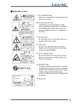
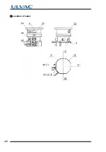
Page 10: ...viii Location of Label...

Page 11: ...n 1 OUTLINE AND DESCRIPTIONS 1 1 Outline 2 1 2 Descriptions 3 1 2 1 Outside Drawing of Pump Unit 3 1 2 2 Power Cable 4 1 2 3 Standard Accessories 4 1 2 4 Option 5 1 2 5 Document List 5 Section 2 IDENT...

Page 12: ...k for Vacuum System 35 5 5 Notes on Transportation 35 Section 6 OPERATION 6 1 Overview 38 6 1 1 Introduction Operation Modes 38 6 2 Startup Preparation 40 6 2 1 Start up Preparation Sequence in LOCAL...

Page 13: ...re Operation 49 6 7 Remote control Connector 51 6 7 1 Specification 51 6 7 2 Pin Assignment 52 6 7 3 Connector 53 6 8 Communication Specifications 54 6 8 1 RS 232C 54 6 8 1 1 Transfer Specifications 5...

Page 14: ...ures 72 9 4 1 Power Failure Counter operation 73 9 5 Alarm Detection Capabilities 74 9 5 1 Movement in Alarm Detection Capabilities ALARM 74 9 5 2 Movement in Alarm Detection Capabilities WARNING 74 9...

Page 15: ...1 1OUTLINE AND DESCRIPTIONS 1 1 Outline 1 2 Descriptions 1 2 1 Outside Drawing of Pump Unit 1 2 2 Power Cable 1 2 3 Standard Accessories 1 2 4 Option 1 2 5 Document List...

Page 16: ...ng vacuum pump to create a high vacuum in a vacuum chamber Typical Applications Semiconductor equipments Industrial equipments R D applications The other ultra high vacuum applications The turbo molec...

Page 17: ...2 1 Outside Drawing of Pump Unit Fig 1 1 UTM2300 Series Description Inlet flange A B C D E F n d UTM2300A MI AVWX UTM2300A MI BVWX VG250 229 286 376 22 5 320 350 12 13 UTM2300A MI AFWX UTM2300A MI BFW...

Page 18: ...Connector Clamp Core Assembling procedure Description Qty Note 1 Gasket inlet flange 1 VG250 O ring gasket ISO250F Not included 2 Bolt set inlet flange VG250 Not included ISO250F Not included 3 Dust...

Page 19: ...series Booklet English Joint Orifice size Description 1 KF10 Clamp Centering with O ring 0 5 mm GP ADAPTOR 0 5 KF10 2 KF10 Dust cap 0 5 mm GP ADAPTOR 0 5 KF DUST CAP 3 UJR 6 35 Male 0 5 mm GP ADAPTOR...

Page 20: ...6 1 1 2 Descriptions This page is intentionally left blank...

Page 21: ...2 2IDENTIFICATION AND FUNCTION 2 1 Pump Main Unit 2 2 Control Panel 2 3 External I F Panel...

Page 22: ...NGE Outlet flange connect a backing vacuum pump or its related pipe connection KF40 4 COOLING WATER PIPELINE Cooling water pipe connector Rc1 4 5 WATER VALVE For protection from dew Refer to Section 5...

Page 23: ...ile power on green lights REMOTE MODE blinks LOCAL MODE 6 ROTATION lamp Operation indicator lamp indicating that the pump s rotor is running green 7 STATUS lamp Operation indicator lamp indicating tha...

Page 24: ...emote control Refer to Section 6 7 Remote control Connector 2 SERIAL connector Connector for RS 232C or RS 485 communication Refer to Section 6 8 Communication Specifications 3 VALVE connector Water v...

Page 25: ...3 3CONSTRUCTION AND PRINCIPLE 3 1 Pump Construction 3 2 Principle of Turbo Molecular Pumping 3 3 Controller...

Page 26: ...ate a disk attached to the drive shaft between the axial magnetic bearings Each magnetic bearing is provided with a gap sensor 9 to detect the rotor position Fig 3 2 illustrates the outline of 5 axes...

Page 27: ...onal Drawing 1 High frequency motor 6 Radial magnetic bearing 11 Outlet flange 2 Drive shaft 7 Axial magnetic bearing 12 Protective net 3 Rotor blade 8 Touch down bearing 13 Cooling water pipeline 4 S...

Page 28: ...lar pump by controlling the following 5 degrees of freedom excluding the rotational degree Z axis of freedom Fig 3 2 Outline of 5 Axes Control X Y Z rotational axis Parallel movement X Y Y Radial disp...

Page 29: ...ply to direct current then uses a three phase inverter to control AC frequency If a power interruption occurs when the rotor is rotating at high speed the power supply unit uses the motor as a generat...

Page 30: ...16 3 3 3 Controller This page is intentionally left blank...

Page 31: ...4 4SPECIFICATIONS 4 1 Standard Specifications for Pump Unit 4 2 The Maximum Allowable Flow Rate 4 3 Standards Fulfilled...

Page 32: ...d 33700 rpm Start up time 9 minutes or less Mounting position In any desired direction Note 5 Vibration level by ULVAC s method 0 01 m or less 0 peak Noise 60 dB A or less Recommended flow rate of pur...

Page 33: ...lamp illuminates Power Interruption Alarm Decelerated while maintaining levitation using regenerative power After decelerating to specified low speed levitation is stopped and rotor is supported by to...

Page 34: ...et Note 5 The outlet port of the turbo molecular pump should face horizontally or vertically when installing the pump horizontally and obliquely Refer to Section 5 1 1 Pump Mounting Direction for deta...

Page 35: ...as type the Assuming the parts connected to the molecular pump inlet and the gas purge flow rate 4 3 Standards Fulfilled Description Gas type Note 1 APC valve temperature Gas purge flow rate The maxim...

Page 36: ...22 4 4 3 Standards Fulfilled This page is intentionally left blank...

Page 37: ...struction and Lifting Method 5 1 2 2 Installation of Turbo Molecular Pump 5 1 3 Example of Piping Connection 5 1 3 1 Connection of Exhaust Line 5 1 3 2 Connection of Cooling Water Line 5 2 Connection...

Page 38: ...zontal inverted or oblique position The outlet port of the turbo molecular pump should face horizontally or vertically when installing the pump horizontally and obliquely When an installation directio...

Page 39: ...ength in preparation for an emergency accident WARNING Ensure that no oil mist or hazardous substances are present in process line as safe ducting procedure when turbo molecular pump is installed to h...

Page 40: ...ump inlet or outlet without fail CAUTION The center of gravity of the pump is indicated in Fig 5 3 Be sure that the pump does not move or fall down during installation or storage CAUTION This pump is...

Page 41: ...ole Size The center of gravity of the pump is shown in Fig 5 3 Fix securely to avoid moving or falling down in the event of an earthquake Fig 5 3 Center of Gravity of the Pump Position Inlet flange Ey...

Page 42: ...the inlet flange of the pump Make installation with the cylindrical part of the bolt not thread part fit in the mating section of flanges When you connect piping or valve between the chamber and the...

Page 43: ...thread Fixing method Only by the inlet flange Inlet flange VG250 ISO250F Bolt size Quantity M12 12 PC M10 12 PC Material Stainless steel SCM435 JIS G 4053 ISO 683 or equivalent Grade A2 70 JIS B 1054...

Page 44: ...flange to the outlet flange of the pump Refer to Fig 5 7 marks are not attached to this turbo molecular pump set Fig 5 7 Example of Exhaust Line When gas purge required connect the gas purge pipeline...

Page 45: ...r pipes to these pumps When connecting the cooling water pipes screw the pipe joint while also holding the nozzle of the pump with a spanner in order to avoid deforming the cooling water pipe as illus...

Page 46: ...ce or circuit breaker of host equipment should be suitably located and easily reached and it should be marked as the disconnecting device for the equipment Check that the part number stuck on the cabl...

Page 47: ...3 5 REFERENCE For the specified power voltage refer to the side panel of the power supply unit Fig 5 11 Power Cable Table 5 4 Power Cable CONNECTION Wire color of power cable Green Yellow Black White...

Page 48: ...inside controller during operation dew warning turns on and the water valve is turns off so that the coolant water should not enter in the pump If the dew is not disappeared for a while dew alarm tur...

Page 49: ...de a flowmeter on the downstream of cooling water line otherwise the turbo molecular pump will shut down and otherwise set up the interlock which the pump cannot start against cut off of water supply...

Page 50: ...36 5 5 5 Notes on Transportation This page is intentionally left blank...

Page 51: ...n 6 4 1 Preparations Prior to Shutting Down Operation 6 4 2 Shutting Down Sequence in LOCAL Mode 6 4 3 Shutting Down Sequence in REMOTE control Connector 6 4 4 Shutting Down Sequence in Other Communic...

Page 52: ...ump cannot be started stopped using two or more of these ways at the same time Determination of which start stop instruction to be followed depends on the operation mode selected There are five operat...

Page 53: ...nector serial connector RS 232C RS 485 When using serial communication the pump can be started or stopped by sending an online request command via the corresponding communication specification To retu...

Page 54: ...blinks when becoming a LOCAL mode 3 Evacuate the turbo molecular pump by using a backing vacuum pump 4 Start up preparation is complete if the pressure in the turbo molecular pump reduces below 200 Pa...

Page 55: ...lamp Under this condition the rotor of the turbo molecular pump is levitated by the magnetic bearing 3 Online command is demanded from the communication means and confirm the mode was switched to the...

Page 56: ...or Fig 2 3 1 3 The pump starts to accelerate and after a few seconds the ROTATION signal turns on In this product of a standard spec ACCELERATION signal Refer to Table 6 4 from the remote control conn...

Page 57: ...mp does not exceed 20 kPa GAUGE CAUTION Electrical energy isolation Lockout Tagout should be achieved by opening the main disconnect device or circuit breaker of host equipment thereby removing power...

Page 58: ...on means The pump deceleration starts Status is changed from NORMAL or ACCELERATION to BRAKE 2 Wait until status changes to STOP status 3 Turn off the POWER switch 4 Stop the cooling water flow 5 If y...

Page 59: ...ble 6 4 3 The NORMAL mode or LOW SPEED mode selection can be made before or after start up 4 Set the low speed value between 25 and 100 of the rated speed in 0 1 increments using the serial communicat...

Page 60: ...to accelerate 6 When the rotational speed reaches 80 of low speed value the NORMAL signal turns on In this product of a standard spec the remote control connector ACCELERATION signal turns off 7 When...

Page 61: ...e pump The BRAKE signal ON Refer to Table 6 4 in this product of a standard spec 4 Once rotation reaches the low speed rotation speed the NORMAL signal ON In this product of a standard spec the BRAKE...

Page 62: ...product of a standard spec 4 If the set low speed value exceed 80 rated speed remote control signals remain unchanged and the pump accelerates 5 When the rated speed is reached the pump stops acceler...

Page 63: ...ARM reset Reset operation when alarm occur Timer Run time Timer and Counter Monitoring and reset maintenance timer Power failure touch down count High speed touch down count MB warning count Setting V...

Page 64: ...un status STATUS Descripition NORMAL ACCELERATION BRAKE STOP E STOP E BRAKE E IDLE Rotating at rated rotation speed Accelerating Decelerating Stopped Alarm is active stopped Alarm is active decelerati...

Page 65: ...uit Connection method By momentary type START STOP switch By alternate type switch Wiring connection Control Pump start by short circuiting 2 and 1 Pump stop by opening 3 and 1 Pump start with the con...

Page 66: ...ion on short circuiting between GND and pin No 4 LOW SPEED 6 Variable speed operation on short circuiting between GND and pin No 6 GND 1 GND Out put ROTATION 17 18 19 During rotation 17 19 open close...

Page 67: ...ion Pin No ALARM 27 28 26 28 EI 03 Note 1 Alarm occurred Open Close Power OFF and no alarm Close Open SEMI E74 Note 2 Power OFF and active alarm Close Open No alarm Open Close WARNING 30 31 29 31 EI 0...

Page 68: ...necessary The shield of the cable should be connected to case 3 Cable length Connection cables can be extended up to 15 meters but may be subjects to errors depending on actual operational environmen...

Page 69: ...Connector Specifications Interface RS 485 2 wire half duplex Synchronous system Asynchronous Transmission rate 9600 bps fixed Character configuration Start bit 1 Data bits 8 Parity None Stop bit 1 Fl...

Page 70: ...for multidropped turbo molecular pump with another pump or pump to which the computer connects is connected to both ends pump 1 through N 1 in Fig 6 6 However connection of the terminator may prevent...

Page 71: ...g on actual operational environment 6 8 3 Connector Fig 6 7 Serial Connector Pin Configuration Figure where connector of panel was viewed from the front NOTICE Serial communication specifications conf...

Page 72: ...58 6 6 8 Communication Specifications This page is intentionally left blank...

Page 73: ...7 7GAS PURGE...

Page 74: ...m or less in element size Use flow control valve to control the flow rate Fig 7 1 Gas Purging Method adaptor with 0 5 mm orifice Table 7 1 Table of Gas Purge Adaptor Start Gas Supply After starting ba...

Page 75: ...ITION 8 1 Recommended Maintenance Intervals 8 2 Turbo Molecular Pump Decontamination 8 3 Touch down Bearing Replacement 8 4 Check of the Rotor Blades 8 5 Power Supply Unit Parts Replacement 8 6 Turbo...

Page 76: ...ity that the following part is exchanged when cleaning TMP 2 Others When exchanging parts it has possibility that other parts are exchanged for improving a reliability Example Old type lower and upper...

Page 77: ...r rotational resistance and require replacement of touch down bearings The replacement of the touch down bearing is done only by ULVAC or an approved service company 8 4 Check of the Rotor Blades Roto...

Page 78: ...Doing so may prevent obtaining the maximum performance To obtain ensure the pump and power supply unit operate safely and perform as designed have parts that exceed their expected service life be rep...

Page 79: ...e performed by ULVAC or an approved service company A copy of this from is printed at the end of this manuals Repair of the Turbo Molecular Pump The following precautions are required before forwardin...

Page 80: ...escribed in Fig 8 1 when lifting this pump on vertical position Need four eyebolts as described in Fig 8 1 when lifting this pump on inverted position There is a possibility that the pump falls when u...

Page 81: ...please pack it surely so as not to damage it by the impact the vibration and the high temperature and humidity environment etc from the outside Please use the packing materials which were used at shi...

Page 82: ...68 8 8 6 Turbo Molecular Pump Return Request This page is intentionally left blank...

Page 83: ...ration 9 3 Nothing Happens After an Operation is Made 9 4 Power Failures 9 4 1 Power Failure Counter operation 9 5 Alarm Detection Capabilities 9 5 1 Movement in Alarm Detection Capabilities ALARM 9 5...

Page 84: ...and or vibration the turbo molecular pump operation is to be stopped immediately But there is possible that a race of touch down bearing Fig 3 1 8 may make sounds for seconds when the pump internal pr...

Page 85: ...mode POWER lamp blinks 6 2 Other causes Check the STATUS lamp is not lights in orange If an alarm is indicated correct the malfunction and reset alarm 9 5 3 Remote STOP signal active but the turbo mol...

Page 86: ...n bearing Table 9 2 shows the number of revolutions and period of time that will elapse before being supported by the touchdown bearing when the power fails at the rated speed Table 9 2 Time and Rotat...

Page 87: ...output signals Note 3 ROTATION Pin no 17 19 18 19 CLOSE goes on OPEN goes on CLOSE goes on OPEN goes on CLOSE goes on OPEN goes on CLOSE goes on OPEN goes on NORMAL Pin no 11 13 12 13 Before power fa...

Page 88: ...p start the protective operations shown in Table 9 6 Table of Alarms 4 The detection error is recorded in the error log 9 5 2 Movement in Alarm Detection Capabilities WARNING 1 STATUS orange lamp Fig...

Page 89: ...as flow rate is not too high 4 1 4 21 24 TMP TEMP MB CABLE TMP OVER TEMP High pump unit temperature Check that the ambient temperature around the pump is within the specified range Check that the temp...

Page 90: ...RT Pump does not rotate Adhesion of reaction products or damage to the protective bearing is the possible cause Remove the pump from the unit and check that the rotor blades rotate smoothly at the inl...

Page 91: ...89 90 MB VIB WARN X1 MB VIB WARN Y1 MB VIB WARN X2 MB VIB WARN Y2 MB VIB WARN Z Transient strong external shock or vibrations Continuous operation is possible However if the shock or vibrations occur...

Page 92: ...Deceleration 32 EI DC DC OVERTEMP Increased temperature inside control system Free run motor stop 34 EI INV OVERCURR Overcurrent ran through the motor 35 EI INV OVERVOLT Defective circuit 36 EI DC DC...

Page 93: ...R ERR X1 Abnormal output signal from the magnetic bearing sensor 62 MB SENSOR ERR Y1 63 MB SENSOR ERR X2 64 MB SENSOR ERR Y2 65 MB SENSOR ERR Z 66 MB DSP ERROR Error in the DSP for magnetic bearing co...

Page 94: ...self diagnostics are abnormal Operation is possible detected during power supply self diagnostics 82 MB SELFCHECK Y1 83 MB SELFCHECK X2 84 MB SELFCHECK Y2 85 MB SELFCHECK Z 86 MB VIB WARN X1 Vibration...

Page 95: ...10 10WARRANTY CLAUSES...

Page 96: ...service conditions described in this document such as temperature range and power etc b Direct export transaction Product which has damage caused by a failure on delivery In the case of direct export...

Page 97: ...he reason of failure was improper use which does not conform to the use condition of this Product j Consumable parts k The SECURITY seal certificates that the product was made or maintenanced by ULVAC...

Page 98: ...84 10 This page is intentionally left blank...

Page 99: ...as purge 18 I inlet flange 8 13 N NET lamp 9 noise 18 O outlet flange 8 13 P port for gas purge 8 POWER lamp 9 Protective 13 R REMOTE connector 10 RESET button 9 ROTATION lamp 9 rotor 13 S SERIAL conn...

Page 100: ...Index Index 2 This page is intentionally left blank...

Page 101: ...ontaminated with reactive products or substances produced by reaction Product model Model Serial No Application Remarks Contaminant Check an applicable box I guarantee that above returned item s is no...

Page 102: ...c http www ulvac co jp en Service Centers http www ulvac co jp en support service center Sales O ces http www ulvac co jp en support sales o ces TEL 0467 89 2261 TEL 03 5769 5511 TEL 06 6397 2286 ULVA...

Reviews: