background image

SK00-2200-AI-144-01(263-43163A) 


INSTRUCTION MANUAL 


TURBO MOLECULAR PUMP 


Model 


UTM300B 


ULVAC, Inc. 

Components Division 

http://www.ulvac.co.jp/ 


Before using this product, be sure to read this operation 

manual. Keep this manual with care to use at any time. 

Summary of Contents for UTM300B

Page 1: ...43163A INSTRUCTION MANUAL TURBO MOLECULAR PUMP Model UTM300B ULVAC Inc Components Division http www ulvac co jp Before using this product be sure to read this operation manual Keep this manual with c...

Page 2: ...om reproducing or copying part or all of this document without permission from ULVAC In an effort to improve the product this document may be revised in the future without notice Every effort has been...

Page 3: ...he proper use of this product Turbo molecular pump repair and or power supply repair can be very hazardous Only trained technicians who are authorized by ULVAC may do service of products Neither overh...

Page 4: ...mergency accident Do not remove or do maintenance the turbo molecular pump before safety has been confirmed Please take an adequate safety precaution based on the result of risk assessment of explosio...

Page 5: ...e ray The pump proper is a precision machine Be careful not to apply abnormal vibration shock impact to it during transportation This pump is not an explosion proof product This pump is not intended t...

Page 6: ...omponents 6 When using the variable speed function to change the pump rotation rate use a rotation rate that does not cause resonance with other devices installed at the site 7 Be careful to prevent a...

Page 7: ...to 5 1 2 Installation of the Pump 3 Do Not Remove Label Do not remove cover or else it may cause somechanges inside and it is failed 4 SECURITY seal This label certificates that the product was made o...

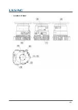
Page 8: ...vii Location of label...

Page 9: ...ts in design or manufacturing during pumping down of air or nitrogen gas Troubles caused by the following are excluded from warranty Troubles that occurred during pumping a gas other than air and nitr...

Page 10: ...esentatives for repair Return charge shall be paid by Buyer Others 1 In case special agreement or memorandum for specifications is made individually it comes in first 2 Buyer shall inform ULVAC when t...

Page 11: ...x This page is intentionally left blank...

Page 12: ...or replacement parts viii Exemption from the warranty viii Disposal of Products and Parts viii LIMITATION OF LIABILITY ix Table of contents xi Section 1 OUTLINE AND DESCRIPTIONS 1 1 Outline 2 1 2 Desc...

Page 13: ...pressure 20 4 3 Maximum continuous backing pressure 20 4 4 Maximum allowable flow rate 21 4 5 Environmental Conditions 22 4 6 Standards Fulfilled 22 Section 5 INSTALLATION 5 1 Installation 24 5 1 1 P...

Page 14: ...erface 40 6 4 4 Shutting Down Sequence in RS 485 communication 41 6 5 Variable Speed Operation 42 6 5 1 Outline 42 6 5 2 Operation from Start up to Low Speed Rotation 43 6 5 2 1 Logic interface Operat...

Page 15: ...lades 57 8 5 Controller Replacement 58 8 6 Turbo Molecular Pump Return Request 59 Section 9 TROUBLESHOOTING 9 1 Vacuum Pressure Rise 62 9 2 Abnormal Noise and or Vibration 62 9 3 Nothing Happens After...

Page 16: ...quence A 5 A3 6 Using the Checksum Byte A 5 A4 TABLE OF COMMANDS A 6 A5 COMMAND DESCRIPTION A 14 A5 1 Operation Mode A 14 A5 2 Operation A 15 A5 3 Run Status A 16 A5 4 Parameters A 17 A5 5 Timer A 17...

Page 17: ...xvi Table of contents This page is intentionally left blank...

Page 18: ...OUTLINE AND DESCRIPTIONS 1 1 Outline 1 2 Descriptions 1 2 1 Outside drawing 1 2 2 Standard Accessories 1 2 3 Option Accessories 1...

Page 19: ...mp to create a high vacuum in a vacuum chamber This pump is not suitable for pumping aggressive or corrosive gases Typical Applications Semiconductor equipments Industrial equipments R D applications...

Page 20: ...ptions 1 2 1 Outside drawing Model Inlet flange A B C D E P C D n d UTM300B AC ICF152 152 4 19 5 122 186 207 130 3 16 8 5 UTM300B AV VG100 185 12 110 164 195 160 8 12 UTM300B AK ISO100 K 130 12 110 16...

Page 21: ...ely 5 Baking heater 230 V 1 230 VAC 200 W Power supply 230 VAC is required separately 6 Interface connector 1 D sub 15 pin female with connector food 7 Interface cable 1 MT 1 24 VDC input RS 485 relay...

Page 22: ...NTIFICATION AND FUNCTION 2 1 Pump Main Unit 2 2 Local Control Panel 2 2 1 Oparational Status 2 2 2 Operation Modes 2 3 Interface Connector 2 4 Optional Accessories 2 4 1 Venting Valve 2 4 2 Cooling Fa...

Page 23: ...Fig 2 1 Pump Main Unit INLET FLANGE Inlet flange joint the turbo molecular pump VG100 ICF152 ISO100 K OUTLET FLANGE Outlet flange connect a backing vacuum pump or its related pipe connection KF16 LOC...

Page 24: ...LOCAL MODE are changed POWER lamp This lamp lights or blinks while power on lights REMOTE mode blinks LOCAL mode NORMAL lamp Operation indicator lamp indicating that the pump s rotor rotating normally...

Page 25: ...on but shifts to protected operation WARNING Malfunction is occurring on the turbo molecular pump or the controller If WARNING occur the pump continues operation Note 1 The rotational speed setting wh...

Page 26: ...3 Interface Connector Fig 2 3 Interface Connector Cooling fan connector Connector for cooling fan Interface connector Connector for power supply RS 485 digital input output analog output Refer to Sect...

Page 27: ...e venting valve opens 10 seconds Note 1 after the STOP signal is input to turbo molecular pump The venting valve closes when a power failure occurs Note 1 The time can be changed within the range of 0...

Page 28: ...10 seconds Note 1 STOP signal is input to the controller and TMP decelerates 10 seconds Note 1 after input STOP signal to controller Venting valve is opened Venting valve continues to open until the...

Page 29: ...263 44455 is fitted to the pump Do not shut off the ventilation or else pump and controller get heated and it is failed In order to secure sufficient air flow passage the domain of less than 50 mm of...

Page 30: ...CONSTRUCTION AND PRINCIPLE 3 1 Pump Construction 3 2 Principle of Turbo Molecular Pumping 3 3 Control system 3...

Page 31: ...the lower stage configurations The profiles of the stator blades and rotor blades are matched for the desired function The shaft 2 is held with the permanent magnet 7 and the ball bearing 6 A touch do...

Page 32: ...olecular Pumping Fig 3 1 Pump Sectional Drawing 1 Motor 6 Ball bearing 11 Protective net 2 Drive shaft 7 Permanent magnet 12 Controller 3 Rotor blade 8 Touch down bearing 4 Stator blade 9 Inlet flange...

Page 33: ...em This system rotates the rotor inside the pump at a rated rotational speed Since it controls the turbo molecular pump externally by remote control the control system includes RS 485 serial interface...

Page 34: ...SPECIFICATIONS 4 1 Specification 4 1 1 Pump Main Unit 4 1 2 Power Supply Unit 4 4 Maximum allowable flow rate 4 5 Environmental Conditions 4 6 Standards Fulfilled 4...

Page 35: ...e 6 N2 100 Pa ambient 25 degrees C Refer to Section 4 3 1000 Pa ambient 25 degrees C Refer to Section 4 3 Maximum allowable flow rate Refer to Section 4 4 Refer to Section 4 4 Mass VG ISO 6 kg 6 3 kg...

Page 36: ...pply Unit Communication Contact REMOTE D sub 15 pin male Screw lock size 4 40UNC cf Section 6 7 Interface Connector Digital input 4 Digital output 4 including 2 relay outputs Analog output 1 rotationa...

Page 37: ...p can be operated continuously when gas flows into the inlet port 4 3 Maximum continuous backing pressure Condition Maximum continuous backing pressure Note 1 Note 2 Gas type Cooling method Ambient te...

Page 38: ...method Gas purge 120 L min 5 25 degrees C N2 Natural convection No 10 mL min Forced air No 100 mL min Ar Forced air No 30 mL min Yes Note 3 40 mL min Note 1 Consult your ULVAC representative before u...

Page 39: ...m Overvoltage category I Pollution degree 2 IP classification 40 Temperature above dew point Operation 5 to 35 degrees C natural convection 5 to 40 degrees C forced air Storage 25 to 65 degrees C Rel...

Page 40: ...5 1 2 Installation of the Pump 5 1 2 1 Instruction and Lifting Method 5 1 2 2 Installation 5 1 3 Example of piping connection 5 1 3 1 Connection of exhaust line 5 2 Connection of electrical supply 5...

Page 41: ...ATION 5 1 Installation 5 1 1 Pump Mounting Direction This turbo molecular pump can be installed in vertical horizontal inverted or oblique position Refer to Fig 5 1 Fig 5 1 Mounting Direction of the T...

Page 42: ...e 3 Place where the pump is inevitably exposed to magnetic field and radioactive ray The pump proper is a precision machine Be careful not to apply abnormal vibration shock impact to it during transpo...

Page 43: ...26 SECTION 5 INSTALLATION 5 1 2 1 Instruction and Lifting Method This puroduct lift the pump in the manner shown in Fig 5 2 Fig 5 2 Lifting Method...

Page 44: ...nlet flange of the pump Make installation with the cylindrical part of the bolt not screw part fit in the mating section of flanges When you connect piping or valve between the chamber and the pump pl...

Page 45: ...steel Grade A2 70 JIS B 1054 ISO 3506 8 8 JIS B 1051 ISO 898 1 Washer Plain washer and spring lock washer Note 1 The main pump body may rotate if abnormality occurs in the pump in the event of acciden...

Page 46: ...Connect a backing vacuum pump or its related pipe connection flange to the outlet flange of the pump Refer to Fig 5 5 marks are not attached to this turbo molecular pump set Fig 5 5 Example of Exhaust...

Page 47: ...ettings 1 5 Input 24 VDC in Voltage supply for the TMP controller Note 1 2 Input START STOP To connect this pin to GND Start pump To open this pin Stop pump 3 Input DI1 To connect this pin to GND RY1...

Page 48: ...change via RS 485 communication Note 3 Venting valve need to be normally closed If you use a normally open valve you have to change the function via RS 485 communication Note 4 Don t connect any pins...

Page 49: ...ALLATION Fig 5 6 Connection of I F connector 5 2 2 Connection I F connector with Interface Cable Option The connection of Interface cable P N 263 44408 is shown in Fig 5 7 Fig 5 7 Interface Cable P N...

Page 50: ...tween the turbo molecular pump and the vacuum chamber close this valve too 5 4 Notes on transportation This product is precision equipment Do not give any strong impact or continuous vibration in tran...

Page 51: ...34 SECTION 5 INSTALLATION This page is intentionally left blank...

Page 52: ...Down Operation 6 4 2 Shutting Down Sequence in LOCAL Mode 6 4 3 Shutting Down Sequence in logic interface 6 4 4 Shutting Down Sequence in RS 485 communication 6 5 Variable Speed Operation 6 5 1 Outli...

Page 53: ...mode selected There are three operation modes as listed below 1 LOCAL mode where switches on the control panel are used for control 2 REMOTE mode where logic interface signals are used for control 3 R...

Page 54: ...hts up The pump can be started or stopped via a contact input or RS 485 communication When using RS 485 communication the pump can be started or stopped by sending an online request command via the co...

Page 55: ...ogic interface 1 Please input the power and check if the POWER lamp Fig 2 2 3 lights 2 Evacuate the turbo molecular pump by using a backing vacuum pump 3 Start up preparation is complete if the pressu...

Page 56: ...nce in logic interface is complete 2 START signal Refer to Table 6 6 is input from the Interface connector 3 The pump starts to accelerate 4 When the rotational speed reaches 80 rated value the Interf...

Page 57: ...pump and vacuum chamber close the valve too 2 When purge gas is being fed into the turbo molecular pump stop the gas feed too 3 When forevacuum valve is provided between the turbo molecular pump and b...

Page 58: ...oil from the backing vacuum pump return the pump internal pressure to atmospheric pressure using dry nitrogen gas after complete shut down of the pump NORMAL lamp goes out to prevent the turbo molecul...

Page 59: ...eration using the LOW SPEED signal input Refer to Table 6 6 3 The NORMAL mode or LOW SPEED mode selection can be made before or after start up 4 Set the low speed value between 25 and 100 of the rated...

Page 60: ...ed value the NORMAL signal turns on 7 When the pump speed reaches the set low speed value acceleration stops and the pump speed is maintained The same operation occurs if the LOW SPEED signal is input...

Page 61: ...OFF Refer to Table 6 6 and starts coasting the pump 4 Once rotation reaches the low speed rotation speed the NORMAL signal ON 5 The pump stops coasting and maintains it current rotation speed If the L...

Page 62: ...logic interface signals remain unchanged and the pump accelerates 5 When the rated speed is reached the pump stops accelerating and the pump speed is maintained 6 5 4 2 RS 485 interface Operation 1 NO...

Page 63: ...N OFF ALARM reset Reset operation when alarm occur Timer Run time Maintenance timer Bearing run time Setting Variable Rotation Speed Low SPEED Changes or sets pump rotational speed Relay Outputs Set a...

Page 64: ...shielded wire and the shield wire should be connected the connector case Table 6 3 Interface connector circuit Input Output Input Output Wiring connection Electric capacity Contact Voltage 30 VDC Cur...

Page 65: ...to 7 15 short circuit Pump stop with the contact open or photo transistor OFF 2 to 7 15 open Electric capacity Refer to Table 6 3 Input rating Direct forward current 50 mA DC reverse voltage 5 V Table...

Page 66: ...2 10 Output RY1 Relay output Venting valve can be connected Note 2 Note 3 This output can be loaded with maximum 24 V 500 mA 11 Output RY2 Relay output This output can be loaded with maximum 24 V 500...

Page 67: ...Not ACC OFF 0006 IDLE ON Not IDLE OFF 0007 Always ON 0008 Always OFF DO1 0000 DO2 0001 Analog output setting 0 10 V 0000 Rotational speed 0 to 100 0001 Motor current 0 to 15 A 0002 Motor temperature 0...

Page 68: ...configuration Start bit 1 Data bits 8 Parity None Stop bit 1 Flow control None Number of units connected Max 32 Connector and Pin assignment Interface Connector Refer to Section 6 7 13 Receive Send D...

Page 69: ...rbo molecular pump with another pump or pump to which the computer connects is connected to both ends pump 1 through N 1 in Fig 6 3 However connection of the terminator may prevent communications with...

Page 70: ...GAS PURGE 7...

Page 71: ...the temperature increases The proper purge gas flow rate is 25 mL min Fig 7 1 is an example of gas purge piping diagram Use a filter 5 m or less in element size Use flow control valve to control the f...

Page 72: ...UMP RECONDITION 8 1 Recommended maintenance intervals 8 2 Turbo Molecular Pump Decontamination 8 3 Bearing Replacement 8 4 Check of the rotor blades 8 5 Controller Replacement 8 6 Turbo Molecular Pump...

Page 73: ...ller Replacement for Power supply unit Process Recommended maintenance intervals Non active gas Sputtering Evaporation and so on and Light load process 3 years 1 Recommended maintenance intervals for...

Page 74: ...as load Mounting direction Bearing exchange period No Vertical Note 1 4 years Directions other than vertical direction 3 5 years Yes Any direction 2 years Note 1 Vertical directions is within 5 Note 2...

Page 75: ...pected service life Doing so may prevent obtaining the maximum performance Replacement of parts inside controller can not be carried out but will exchange the whole controller The replacement of the c...

Page 76: ...ump with an inert gas The pump interior must be adequately purged with inert gas before uninstalling from the unit 2 The customer is required to submit MSDS Material Safety Data Sheet sheets and infor...

Page 77: ...60 SECTION 8 TURBO MOLECULAR PUMP RECONDITION This page is intentionally left blank...

Page 78: ...Noise and or Vibration 9 3 Nothing Happens After an Operation is Made 9 4 Power Failures 9 5 Alarm Detection Capabilities 9 5 1 Movement in Alarm Detection Capabilities ALARM 9 5 2 Movement in Alarm D...

Page 79: ...rbo molecular pump to start coasting and the ALARM lamp Fig 2 2 5 lights Do not suddenly increase the pressure or let atmospheric air enter the pump during pump operation 9 2 Abnormal Noise and or Vib...

Page 80: ...aintained push the RESET button change to LOCAL mode POWER lamp blinks 6 2 Other causes Check the ALARM lamp is not lights If an alarm is indicated correct the malfunction and reset alarm 9 5 3 Remote...

Page 81: ...ore power failure indication goes on Before power failure indication goes on Before power failure indication goes on Before power failure indication goes on NORMAL LED Before power failure indication...

Page 82: ...on 3 The pump start the protective operations shown in Table 9 6 Table of Alarms 9 5 2 Movement in Alarm Detection Capabilities WARNING 1 ALARM lamp Fig 2 2 5 flashes 2 The logic interface WARNING sig...

Page 83: ...in the CPU for inverter control 5 46 47 MOTOR OVERSPEED EI R SPEED ERROR Rotation detection signal from the motor cannot be detected correctly Check that equipment causing noise is not used around th...

Page 84: ...EI CONT TEMP WARN Temperature increase in the control system Check that the ambient temperature around the pump is within the specified range In the case of forced air cooling spcefication check that...

Page 85: ...motor 35 EI INV OVERVOLT Increase the 24 VDC power supply 36 EI DC DC LOW VOLT Decrease the 24 VDC power supply 43 EI PARAM ERROR Stored parameters are not correct 44 EI CPU ERROR Error in the CPU for...

Page 86: ...g Sequence A3 6 Using the Checksum Byte A4 TABLE OF COMMANDS A5 COMMAND DESCRIPTION A5 1 Operation Mode A5 2 Operation A5 3 Run Status A5 4 Parameters A5 5 Timer A5 6 History A5 7 Settings A5 8 Shared...

Page 87: ...the operation mode to RS 485 2 Operation START STOP and RESET operations are available in the RS 485 operation mode Also the speed setting can be made using the set value write function 3 Checking tur...

Page 88: ...ead of RS 232C to extend the communication cable length When the multi drop function is turned on the network ID portion of the sent character strings Refer to Section A3 is enabled and the event comm...

Page 89: ...Answers Character Hex code Description Number of bytes M 4d Command header characters 2 J 4a 0 30 Network ID Multi drop function OFF 01 fixed Multi drop function ON 01 to 32 RS 485 settings 99 fixed N...

Page 90: ...ion from the initial command header MJ to the carriage return code received last is processed as an answer Initialize the receive buffer after the answer character string is acquired from the receive...

Page 91: ...n RU None Failure occurred RF aa 1 Failure elimination RC None Operation invalid RV None Run status Command Run status check CS None Answer Stop NS aa 1 Acceleration NA aa 1 Normal rotation NN aa 1 Fr...

Page 92: ...ponding to the protection system Refer to Table 9 6 Table of Alarms and Table 9 7 Table of Warnings 2 aa Parameter number decimal Refer to Table A 4 Table of Parameters 3 aa Parameter number decimal R...

Page 93: ...g Rotational speed NORMAL Table A 7 No 03 Low rotation speed Low speed 100 0 Table A 7 No 04 or No 08 Warning output setting WARNING DISPLAY ON Table A 7 No 10 RY1 relay output 1 setting Delay Venting...

Page 94: ...SA NN Run status when the failure occurred Data is identical to CS command answer 6 Rotational speed 4 0000 0100 Speed when the failure occurred Format is identical to 09 in Table A 4 7 Motor current...

Page 95: ...150 Motor temperature Example 100 degrees C 0100 Table A 5 Table of Timer Name Range Description and format 01 Run time 00000 99999 Integrating timer while the pump is rotating Can not be reset Reset...

Page 96: ...Speed when the failure occurred Format is identical to 09 in Table A 4 6 Motor current 4 0000 0150 Motor current in the event of a fault Format is the same as No 04 in Table A 4 7 Reserved 6 000000 99...

Page 97: ...ctor and serial communication 80 RY1 relay output 1 operation setting 0000 0004 RY1 output setting 0000 RY1 is ON when DI1 is ON 0001 RY1 is ON when DI1 is OFF 0002 Always RY1 ON 0003 Always RY1 OFF 0...

Page 98: ...signal is input to controller 0030 Venting valve will open after 30 seconds passes when the controller is input STOP signal Table A 8 List of RS 485 Settings Name Range Description and Configuration...

Page 99: ...by the local switch In this LOCAL mode the operation of the pump is valid only by local switch LR Operation mode REMOTE This answer is returned when the operation mode is REMOTE This operation mode ca...

Page 100: ...n RB Deceleration Start This answer is not used for UTM300B RU Coasting Start This answer is returned after the coasting is started on a STOP operation RC Failure elimination This answer is returned i...

Page 101: ...ed after a failure occurs The 2 character alarm code is returned as the sub command FF Failure Free run This answer is returned when the pump is free running neither accelerating nor decelerating afte...

Page 102: ...ommand A5 5 Timer Commands TR Read timer Reads the timer value for a designated timer number Sends the 2 character timer number as the sub command Refer to Table A 5 Table of Timer for timer number TC...

Page 103: ...y data corresponds to the designated alarm history number Returns the 2 character alarm history number as the sub command Commands GJ Read alarm history 2 Reads the alarm history for a designated alar...

Page 104: ...s invalid Returns the 2 character settings number as the sub command Commands SU Read user memo Reads the character string in the user memo SX Write user memo Overwrites the character string in the us...

Page 105: ...possibility not to be able to communicate Answers Note 1 DB Answer returned when finished restoring RS 485 settings to factory settings Note 1 a Communication between customer equipment and turbo mole...

Page 106: ...MJ01LR96 Operation Mode Change Operation mode changed to REMOTE MJ01LD88 Invalid Request When in RS 485 mode MJ01LL90 Invalid Request When in LOCAL mode TMP Operation MJ01RT9E START Operation START o...

Page 107: ...er Clear timer 03 Number of power failure touch downs MJ01TA03000000304 0515000304051500C 4 Send Timer Value Sets timer number 03 0 to date time cleared Sets reset date time to date time when clear co...

Page 108: ...ORMAL MJ01SW030001C6 Write Settings Overwrite settings number 03 1 MJ01SA030001B0 Send Settings Value Settings number 03 1 Rotational speed LOW SPEED Others MJ01AA7A Undefined Command When undefined c...

Page 109: ...tion mode is shifted to RS 485 ON LINE in response to ON LINE request of operation mode command from RS 485 communication port only operation by the operation request command from computer is effectiv...

Page 110: ...Done But Receivable Messages are Invalid 1 Check the transmission rate of the computer A8 3 Characters Get Disordered from Time to Time Then Resulting in CHECKSUM Error 1 Remove the cable from equipm...

Page 111: ...A 26 Appendix A COMMUNICATIONS This page is intentionally left blank...

Page 112: ...ontrol Panel 7 cooling fan connector 9 I I F panel 6 inlet flange 6 15 interface connector 9 N NORMAL lamp 7 O outlet flange 6 15 P permanent magnet 14 15 POWER lamp 7 R RESET button 7 rotor 15 RS 485...

Page 113: ...This page is intentionally left blank...

Reviews: