6.1
Overview
39
6
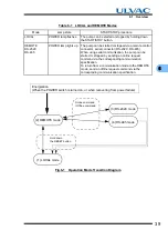
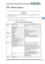
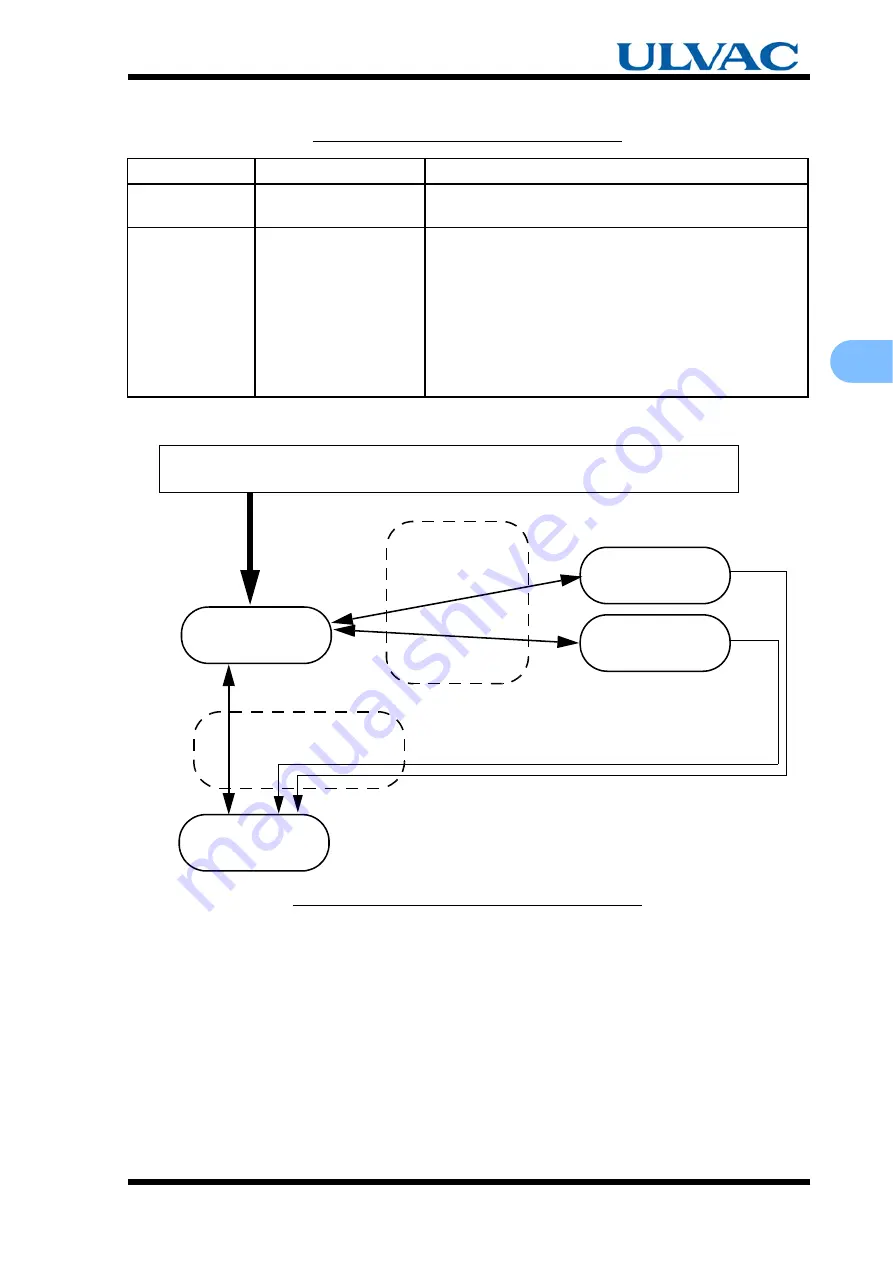
Table 6-1
LOCAL and REMOTE Modes
Fig.6-1
Operation Mode Transition Diagram
Mode
Lamp state
START/STOP procedure
LOCAL
POWER lamp flashes.
The pump can be started or stopped by holding down
the START/STOP button.
REMOTE
RS-232C
RS-485
POWER lamp lights up. The pump can be started or stopped via a remote control
connector, serial connector (RS-232C, RS-485).
When using serial communication, the pump can be
started or stopped by sending an online request
command via the corresponding communication
specification.
To return from a communication mode to the REMOTE
mode, send an offline request command via the
corresponding communication specification.
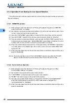
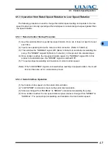
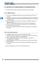
(1) LOCAL mode
Hold down
(3) RS-232C mode
(4) RS-485 mode
Online command
/ Offline command
(When the POWER switch is turned on, or when recovering from power failure)
Energization
(2) REMOTE mode
the RESET button
Summary of Contents for UTM3400 Series
Page 2: ...This page is intentionally left blank...
Page 10: ...viii Location of Label...
Page 20: ...6 1 1 2 Descriptions This page is intentionally left blank...
Page 21: ...2 2IDENTIFICATION AND FUNCTION 2 1 Pump Main Unit 2 2 Control Panel 2 3 External I F Panel...
Page 30: ...16 3 3 3 Controller This page is intentionally left blank...
Page 36: ...22 4 4 3 Standards Fulfilled This page is intentionally left blank...
Page 50: ...36 5 5 5 Notes on Transportation This page is intentionally left blank...
Page 72: ...58 6 6 8 Communication Specifications This page is intentionally left blank...
Page 73: ...7 7GAS PURGE...
Page 82: ...68 8 8 6 Turbo Molecular Pump Return Request This page is intentionally left blank...
Page 95: ...10 10WARRANTY CLAUSES...
Page 98: ...84 10 This page is intentionally left blank...
Page 100: ...Index Index 2 This page is intentionally left blank...


