SECTION 6
OPERATION
52
6
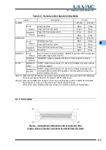
6.7.2 P
in Assignment
Table 6-4
Remote-control Signals
(Note 1) Don't connect any pins other than specified above.
(Note 2) It takes 6 seconds until it comes to show that this signal is correct, after POWER switch is
turned on.
(Note 3) "STOP" signal is prior to "START" signal.
(Note 4) One reset signal is received each time when the contact closes. Repeatedly short and open
the contact to input multiple reset signals.
(Note 5) It is possible to change movement by remote-control signal settings of serial communication.
(Refer to Table 6-5)
Name
Pin No.
(Note 1)
Operation
(Note 2)
Electric
spec
In-
put
START
2
Starting operation on short-circuiting between
GND and pin No. 2. (Note 3)
Contact
Input
STOP
3
Pump stop by opening GND and pin No. 3.
(Note 3) (Note 5)
RESET (Note 4)
4
Resetting operation on short-circuiting between
GND and pin No. 4.
LOW SPEED
6
Variable speed operation on short-circuiting
between GND and pin No. 6.
GND
1
GND
Out-
put
ROTATION
17
18
19
During rotation
(17)-(19) open
→
close (make contact)
(18)-(19) close
→
open (break contact)
Contact
Output
Contact
capacity
(resistance
load)
30 VDC
1 A
NORMAL
11
12
13
During rotational speed is more than 80 % rated
value
(11)-(13) open
→
close (make contact)
(12)-(13) close
→
open (break contact)
ACCELERATION
8
9
10
During acceleration
(8)-(10) open
→
close (make contact)
(9)-(10) close
→
open (break contact)
BRAKE
14
15
16
During deceleration
(14)-(16) open
→
close (make contact)
(15)-(16) close
→
open (break contact)
REMOTE
20
21
22
Remote-controlled operation is available (Note 5)
(20)-(22) open
→
close (make contact)
(21)-(22) close
→
open (break contact)
ALARM
26
27
28
Against ALARM (Note 5)
(26)-(28) open
→
close (make contact)
(27)-(28) close
→
open (break contact)
WARNING
29
30
31
Against WARNING (Note 5)
(29)-(31) open
→
close (make contact)
(30)-(31) close
→
open (break contact)
CONNECTION
23
25
(23)-(25) Always closed
Summary of Contents for UTM3400 Series
Page 2: ...This page is intentionally left blank...
Page 10: ...viii Location of Label...
Page 20: ...6 1 1 2 Descriptions This page is intentionally left blank...
Page 21: ...2 2IDENTIFICATION AND FUNCTION 2 1 Pump Main Unit 2 2 Control Panel 2 3 External I F Panel...
Page 30: ...16 3 3 3 Controller This page is intentionally left blank...
Page 36: ...22 4 4 3 Standards Fulfilled This page is intentionally left blank...
Page 50: ...36 5 5 5 Notes on Transportation This page is intentionally left blank...
Page 72: ...58 6 6 8 Communication Specifications This page is intentionally left blank...
Page 73: ...7 7GAS PURGE...
Page 82: ...68 8 8 6 Turbo Molecular Pump Return Request This page is intentionally left blank...
Page 95: ...10 10WARRANTY CLAUSES...
Page 98: ...84 10 This page is intentionally left blank...
Page 100: ...Index Index 2 This page is intentionally left blank...


