background image


  YK15-0009-DI-002-04 

Contents-1 


Table of Contents 

0. Before Using This Product ....................................................................................................................... i


0.1 Safety Symbol Marks ......................................................................................................................... ii


0.2 Meanings of Safety Symbol Marks .................................................................................................... ii


0.3 Safety Precautions............................................................................................................................ iii


0.4 Types and Descriptions of Warning Labels Displayed on This Machine and Displayed Positions . ix


0.5 Acceptance and Storage of the Pump .............................................................................................. xi


0.5.1 Unpacking/Acceptance of the Pump .......................................................................................... xi


0.5.2 Transfer ..................................................................................................................................... xii


0.5.3 Ambient Condition for Storage, Install and Operation ............................................................. xiii


0.6 Protective Device ............................................................................................................................ xiv


1.


For Your Safety Use ............................................................................................................................ 1


1.1 This Product Intrinsic Hazardous Nature and Safety Measures ...................................................... 1


1.1.1    !    Danger    Leakage of dangerous gas and dangerous materials......................................... 1


1.1.2    !    Warning    Transfer of heavy material ................................................................................. 1


1.1.3    !    Warning      Electric shock ................................................................................................... 2


1.1.4    !    Warning    Explosion ............................................................................................................ 2


1.1.5    !    Caution    High temperature ................................................................................................ 2


1.2 Safety Data Sheet

SDS

 ................................................................................................................. 3


2.


Pump Outline ....................................................................................................................................... 4


2.1 Characteristics .................................................................................................................................. 4


2.2 Performance Specifications .............................................................................................................. 7


2.3 System Flow ..................................................................................................................................... 8


2.4 Dimensional drawing ........................................................................................................................ 9


2.5


Pump Performance ..................................................................................................................... 13


2.5.1 Ultimate Pressure ..................................................................................................................... 13


2.5.2 Pumping Speed ........................................................................................................................ 13


2.5.3 Power Requirements ................................................................................................................ 15


3. Mounting ............................................................................................................................................... 16


3.1 Storage/ Installation ........................................................................................................................ 16


3.2 Lubrication ...................................................................................................................................... 17


3.3 Inlet port Piping ............................................................................................................................... 18


3.4 Outlet port Piping ............................................................................................................................ 19


3.5 Electrical Connection ...................................................................................................................... 20


4. Operation .............................................................................................................................................. 24


4.1 Caution on Operation ..................................................................................................................... 24


4.2 Operation Start ............................................................................................................................... 26


Summary of Contents for VD30C

Page 1: ...TION MANUAL OIL SEALED ROTARY VACUUM PUMP VD30C VD40C VD60C VD90C Before using this product be sure to read this operation manual Keep this manual with care to use at any time ULVAC Inc Components Div...

Page 2: ......

Page 3: ......

Page 4: ......

Page 5: ...ensured if any of the devices put together did not conform to same regulations or this product itself was modified ULVAC shall be not liable to guarantee performance and safety in such cases above An...

Page 6: ...ustrated below 0 2 Meanings of Safety Symbol Marks DANGER If the user makes a mistake in handling it indicates an imminent possibility that the user is subject to death or heavy injury WARNING If the...

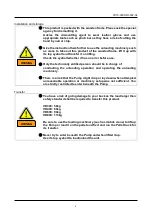
Page 7: ...and operation methods of this product DANGER Use of the toxic combustible or combustion susceptible gas other than inactive gas is not allowed as there is a risk of leakage of the gas from the Pump u...

Page 8: ...ast user that uses this product WARNING You are kindly requested to acknowledge that specifications and or price of this product and description of the Instruction Manual are subject to change without...

Page 9: ...ically entitled person should be in charge of conducting the unloading operation and operating the unloading machinery There is a risk that the Pump might drop or lay down when attempted unreasonable...

Page 10: ...wiring work might cause a fire Conduct the wiring operation correctly in compliance with laws and rules concerning the safety e g Fire Defense Law Electric Equipment Technology standard Internal line...

Page 11: ...charge of dismantling repairing or remodeling this product You have a risk of getting injured or electrical shock by a fire or erroneous move Do not touch the Motor vacuum pump or piping during the Pu...

Page 12: ...the system The Inlet and outlet piping remains very hot while after having stopped the Pump Be sure to take it off after the Pump has sufficiently cooled down Make airtight completely the Pump exhaust...

Page 13: ...ture Ensured pressure value of the Pump shall be 0 03MPaG 0 3kg cm2G Gauge pressure Do not run the Pump on blocking the Exhaust outlet or putting any device that might hamper gas passage onto the outl...

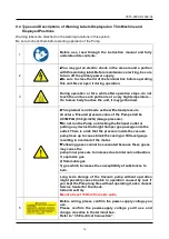
Page 14: ...andard for Motor Operated Air Compressors Vacuum Pumps and Painting Equipment by replacing the warning label according to the figure below Fig 2 Warning Label replacement Hazardous voltage Hot heating...

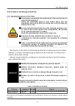
Page 15: ...cted to enter beneath the Pump Upon delivery of this product check first that the delivered is exactly what you have ordered and there is no break or damage through transport or the like Claim after u...

Page 16: ...e required to transfer this product VD30C 58kg VD40C 60kg VD60C 90kg VD90C 113kg Be sure to use the loading machinery such as mobile crane to lift up the Pump or load it on the pallet and fix it and r...

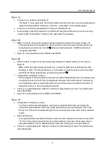
Page 17: ...G Miscellaneous for both storage and operation a There shall be no corrosion behavior or explosive gas b There shall be no freeze or dew formation c There shall be no dust d It shall be in house e Ano...

Page 18: ...cluded VD90C The Pump has eight holes The Pump is fixed with four bolts Four places of outside or center side of the Pump The detail of the holes position Refer to the Fig 3 Fig 10 0 6 Protective Devi...

Page 19: ...t Intrinsic Hazardous Nature and Safety Measures 1 1 1 1 Danger Leakage of dangerous gas and dangerous materials 1 1 1 2 Warning Transfer of heavy material 1 1 1 3 Warning Electric shock 2 1 1 4 Warni...

Page 20: ...the Suction Inlet 36 5 2 7 Checking Noise and Abnormal Vibration 36 5 2 8 Checking Coupling and Spider 37 5 2 9 Checking Oil Mist Trap option 38 5 2 10 Checking drain valve 38 5 3 Checkup after stora...

Page 21: ...ation and oil level indication 17 Fig 15 Connection to vacuum chamber example 18 Fig 16 Recommended connection diagram 20 Fig 17 Electrical wiring diagram 20 Fig 18 Installation example VD90C 30 Fig 1...

Page 22: ...st any hazardous gas such as toxic and combustible When you check the Pump please wear a brace that supports the toxic substances that exhaust the Pump To overhaul or dispose ask the special agency to...

Page 23: ...ssure inside the Pump rises up and the Pump explodes Ensured pressure value of the Pump is 0 03MPaG 0 3 kg cm2 G Gauge pressure Check the Exhaust side pressure of the Pump If it was over 0 03 MPaG 0 3...

Page 24: ...u are in need Read it with attention to acknowledge the toxic characteristics described on the SDS Please do not use the chemical material except the above mentioned chemical material vacuum pump oil...

Page 25: ...he exhaust operation in the vicinity of the atmospheric pressure the stable exhaust performance can be obtained 4 Employment of hydraulic oil anti sucking system If the power fails or the Pump is stop...

Page 26: ...cation for special application Following specification is available to meet various applications Table 3 Optional specifications and gasket material oil type comparison table Specification Applicable...

Page 27: ...the high load that the Pump temperature exceeds more than 80 Independent oil filling to oil seal Oil is supplied to the atmospheric seal part oil seal independently from circulating oil by mounting t...

Page 28: ...n means repeat pumping down between atmospheric pressure and vacuum in short term or long time operation at 10 000 Pa 75 Torr or higher Recommended oil mist trap Optional 6 TM201 for low load operatio...

Page 29: ...YK15 0009 DI 002 04 8 2 3 System Flow Power supply is required And you prepare wiring safety circuit and exhaust processing equipment etc Fig 3 Location of vacuum pump in host device...

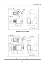
Page 30: ...YK15 0009 DI 002 04 9 2 4 Dimensional drawing Fig 4 Dimensional drawing VD30C VD30C F VD30C N Fig 5 Dimensional drawing VD40C VD40C F VD40C N...

Page 31: ...YK15 0009 DI 002 04 10 Fig 6 Dimensional drawing VD60C Fig 7 Dimensional drawing VD90C...

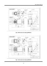
Page 32: ...YK15 0009 DI 002 04 11 Fig 8 Dimensional drawing VD30C H VD30C B Fig 9 Dimensional drawing VD40C H VD40C B...

Page 33: ...YK15 0009 DI 002 04 12 Fig 10 Dimensional drawing VD60C H Fig 11 Dimensional drawing VD90C H...

Page 34: ...e site shall likely to raise the ultimate value higher than the catalogue value as the vacuum gauge was put far away from the Pump or maybe affected by the water drop rust or other substances attached...

Page 35: ...pasitance Manometer VD30C 50Hz VD30C 60Hz VD40C 60Hz VD40C 50Hz Fig 12 Pumping speed curves MODEL VD30C VD40C 0 20 40 60 80 100 0 1 1 10 100 1000 10000 100000 Pumping Speed m 3 hour Pressure Pa Gas Ba...

Page 36: ...n pressure was between 3 104 4 104 Pa Operation opening the gas ballast valve would require larger motive energy at all the time as its compression work is large even the suction pressure was small No...

Page 37: ...e regarding the electricity machinery cargo vacuum and so on Be sure to clear any energy sources e g electricity coolant and so on of this product before installing or removing this product 3 1 Storag...

Page 38: ...ould the oil touched to your hand are entered in your eye immediately follow the emergency treatment described on the SDS CAUTION Ensure to use the vacuum pump oil designated by ULVAC Operation using...

Page 39: ...inlet in order not to allow any foreign substance enter inside Should the Pump sucked the water or substance such as dust powder and so on it would impair the ultimate pressure and further cause a tr...

Page 40: ...osion and or give damage on pump parts when discharged through vacuum pump Be sure to use pipes made of metal electricity conducting material Ensure also to take a grounding If to exhaust any combusti...

Page 41: ...ass utilities by changing wire connection in the motor terminal box because multi voltage motor for both 200V and 400V classes is used for this pump WARNING The motor is set up the connection matched...

Page 42: ...onsidering the voltage drop of the wire Typically the voltage drop please to be within 2 of the rated voltage of the motor Voltage drop calculation 3 wire resistance km Wiring length m motor rated cur...

Page 43: ...to ground the motor ground terminal 200V 240V Ground to 100ohm or less 380V 460V Ground to 10 ohm or less Use a safety circuit which keeps the motor from starting a fire which is caused by over curre...

Page 44: ...380 50 4 9 400 50 5 1 415 50 5 2 380 60 4 5 400 60 4 4 440 60 4 3 460 60 4 3 200 50 14 4 220 50 14 1 240 50 15 0 200 60 13 8 220 60 12 8 230 60 12 6 240 60 12 3 380 50 8 1 400 50 8 4 415 50 8 7 380 6...

Page 45: ...mended to replace the first Pump oil within ten days after operation start and see how it got dirty to determine the oil replacement cycle If the Pump breathes in a lot of water or the like you should...

Page 46: ...is recommended to install the oil recovery mechanism Option The maintenance cycle might become shorter 3 Upon performing the continuous operation at the high suction pressure the oil temperature becom...

Page 47: ...ouch the Motor and Pump unit as they become high temperature during operation Apply an appropriate protection to avoid touching the surface as necessary Refrain from touching any part other than valve...

Page 48: ...mp cools down after having stopped operation Apply an appropriate protection to avoid touching the surface as necessary CAUTION Ensure to close the Main valve and open the Leak valve to stop the Pump...

Page 49: ...ecified process performance Note further that keeping the gas ballast valve open when not breathing in the condensed gas shall cause the Pump oil splashing and power loss and further rise the ultimate...

Page 50: ...72 standard oil 2 ULVOIL R 42 For cold district in winter In the case of ambient temperature 4 10 IMPORTANT When temperature is low and a pump does not run warm up the Pump oil or turn the Pump on and...

Page 51: ...IL MIST TRAPS Fig 18 Installation example VD90C WARNING Limit value of the pressure inside the Pump is 0 03MPaG 0 3kg cm2G Gauge pressure If the pressure is raised filter element please exchange We re...

Page 52: ...ring high overload operation continuous operation at 1000Pa or more repeated operation between atmospheric pressure and vacuum 1 Whether the Vacuum oil pump oil volume is between two level lines or no...

Page 53: ...Erroneous wiring work might cause a fire Conduct the wiring operation correctly in compliance with laws and rules concerning the safety e g Fire Defense Law Electric Equipment Technology standard Int...

Page 54: ...mmended to replace the first Pump oil within 10 days after operation start and see how it got contamination viscosity and discoloring to determine the oil replacement cycle Check and replace the oil p...

Page 55: ...anty You should also replace the oil if breathed in the solution to deteriorate lubrication of the oil as it would also cause biting inside You shall have a risk if breathed in the solution in operati...

Page 56: ...ot be attained by oil change sludge or other deposit may have collected on the bottom of the Pump case In that event overhaul is required Contact your local ULVAC organization or representative DANGER...

Page 57: ...ogged by the dust contained in the gas breathed in from the Vacuum chamber and thus the Pump performance might be impaired If there is the metal mesh is dirty please wash that Further it is anticipate...

Page 58: ...upling Replace the spider with a new one 6 Put the new coupling spider in one of the coupling Meet the ratchet of both couplings and mount the Pump unit in the medium case 7 Put the M8 nut x 4 and spr...

Page 59: ...sure We recommend you to install a Pressure monitor Refer to the Instruction Manual of the oil mist trap as for the install position of the pressure monitor For the pressure monitor mounting position...

Page 60: ...ice Center close to you listed at the end of the document as for the overhaul Do not forget to fill and submit the Contamination certificate enclosed in the end of the document WARNING We would be obl...

Page 61: ...the overhaul replacement of the cylinder rotor cover and so on 5 4 5 Reactive agent accumulated inside the Pump while the Pump was stopped after having exhausted the reactive gas Conduct the overhaul...

Page 62: ...d so on 5 4 13 Water absorption expands the vanes Conduct the overhaul replace the vanes 5 4 14 Components inside the Pump have burnt out Conduct the overhaul 5 4 15 Temperature is low a turn the Pump...

Page 63: ...tter 5 4 4 Cooling fan is touching Check the Cooling fan mount and clear the error 5 2 8 5 4 5 The oil is not circulating a Oil pit of the Cover or the like is clogged b Oil distributor valve has a tr...

Page 64: ...matches the measurement pressure range and correctly calibrated one to measure the pressure 2 5 1 4 Pipe connected to the Suction inlet is thin or connection distance is long Connect a pipe wider tha...

Page 65: ...2 2 8 There is a leak in the pipe connecting with the Pump Use a Leak detector or the like to find out the leak position and stop it 3 3 9 Not using the ULVAC genuine oil Conduct the overhaul of the...

Page 66: ...e overhaul Inside cleaning 3 2 5 2 1 5 2 2 4 Suction gas is hot Install a cooling device such as the as cooler on the suction side 5 Area around the Pump is enclosed Make the ventilation available 0 5...

Page 67: ...continuous operation under high suction pressure Adjust the pressure Lot of oil mist blowing out of the Exhaust outlet 1 Pump is filled over the specified volume Drain the oil until it gets the specif...

Page 68: ...Pay attention to execute maintenance work You should replace with the nitrogen gas completely the Pump that exhausted any special gas Note further that only the entitled person for special gas handlin...

Page 69: ...any toxic gas Note that you are requested to bear the cost and charges relating to the disposal WARNING You should ask a special disposal agency for the disposal particularly if the Pump has exhausted...

Page 70: ...y Products not satisfying the standard specifications although this product is used under the service conditions described in this document such as temperature range and power etc 2 Direct export tran...

Page 71: ...dary damage to Buyer by the reason that third party sued ULVAC for patent infringement 9 ULVAC engineer decided the reason of failure was improper use which does not conform to the use condition of th...

Page 72: ...YK15 0009 DI 002 04 51 9 Main Replacement Parts Fig 20 Exploded perspective view Different parts between VD30C VD40C and VD60C VD90C...

Page 73: ...alve valve seat KA9002 026 02 1 1 55 O ring S105 3 3 M 90 1 1 KA9101 022 01 1 KA9202 026 02 1 1 O ring S120 3 3 83 Coupling for pump KA9002 030 02 1 1 KA9202 022 01 1 29 2st exhaust valve valve guide...

Page 74: ...1 NBR 1 Silicone rubber 1 FKM 1 52 O ring S8 FKM 3 NBR 3 Silicone rubber 3 FKM 3 53 O ring S18 FKM 1 NBR 1 Silicone rubber 1 FKM 1 54 O ring S60 FKM 1 NBR 1 Silicone rubber 1 FKM 1 55 O ring S105 FKM...

Page 75: ...2 SUS 3 SUS 2 SUS 3 27 2nd exhaust valve plate For first exhaust valve SUS 2 56 O ring AS568 274 FKM 1 48 O ring P10A FKM 1 51 O ring P48 FKM 1 52 O ring S8 FKM 3 53 O ring S18 FKM 1 54 O ring S60 FKM...

Page 76: ...uct warranty period Table 11 Making format for names and contents of hazardous substances or elements Name of parts Hazardous substances or elements Pb Hg Cd Cr6 PBB PBDE Body indicating that content...

Page 77: ...ion Remarks Contaminant Check an applicable box I guarantee that above returned item s is not contaminated with harmful substances Above returned item s is contaminated with the following harmful subs...

Page 78: ......

Reviews: