
12
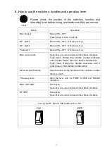
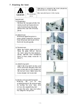
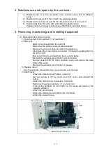
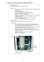
7. Attaching the hoist
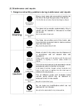
Caution
Do not attempt
alone
Attaching or removing the hoist should be
done by two or more people.
May cause back pains or other injuries.
Attachment
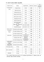
1) Preparation
Remove the hexagonal bolts, flat
washers and spring washers (4
sets) from the hoist mounting
plate on the rear left of the top
panel.
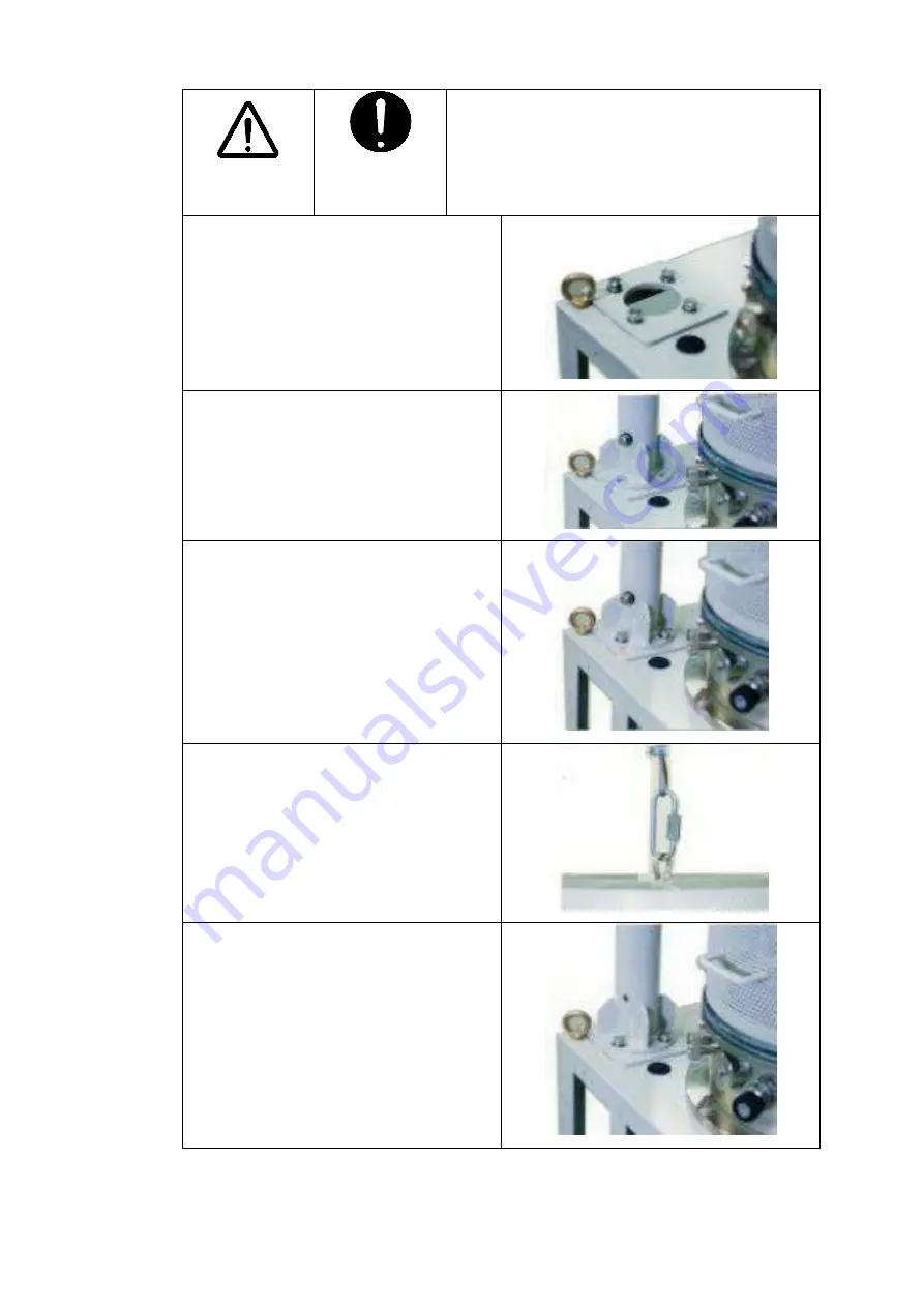
2) Attach hoist
With the weight-fixing bolt in
place, get two people to carry the
hoist into place and insert it into
the hoist mounting plate.
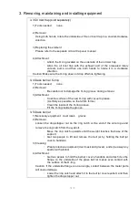
3) Secure hoist
Move the hoist’s upper arm so it
faces the glass bell jar. Secure
the hoist using the flat washers,
spring washers and hexagonal
bolts (in that order) removed in
step (1).
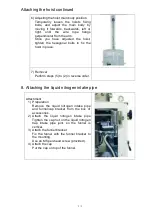
4) Attach ring catch
Attach the ring catch on the end
of the wire rope hanging from the
end of the arm to the eyebolt on
the bell jar cover. Make sure the
loose stopper nut is secured.
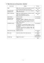
5) Remove the weight-fixing bolt
Remove
the
nut
of
the
weight-fixing bolt, lift up the weight
by pulling the wire rope, and
remove the weight-fixing bolt.
Loosen the wire rope and allow
the weight to hang down.


