background image


23


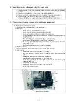
  3. Removing, maintaining and installing equipment 


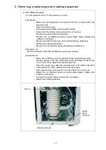
  3-3 Oil mist trap (sold separately)   


1) Tools needed        none 


2) Removal 

Using both hands, rotate the underside of the oil mist trap in a counter-clockwise 

direction. 


3) Replacing the element 

Please refer to the separate oil mist trap user manual. 
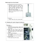
 

4) Attachment 

・ 

Attach the O-ring located on the underside of the oil mist trap.   

・ 

Align  the  oil  mist  trap  with  the  exhaust  port  of  the  oil-sealed  rotary 
vacuum  pump,  and  then  use  both  hands  to  rotate  it  in  a  clockwise 
direction. 

Caution: Make sure the O-ring does not drop off while tightening.


  3-4 Glass bell jar O-ring


1) Tools needed        none 

2) Removal 

・ 

Be careful not to damage the O-ring groove during removal. 

3) Attachment 

・ 

Coat the surface of the new O-ring with vacuum grease.   

・ 

(As thinly as possible, so that a film forms) 

・ 

Clean the inside of the O-ring groove. 

・ 

Fit the O-ring inside the groove.
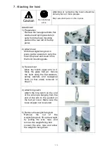
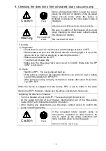
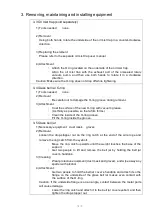


  3-5 Glass bell jar 


1) Necessary equipment    dust mask      gloves 

2) Removal 

Loosen  the  drop-stopper  nut  on  the  ring  catch  at  the  end  of  the  wire  rope  and 

remove the ring catch from the eyebolt. 

・ 

Move  the  ring  catch  upwards  until  the  weight  touches  the  base  of  the 
support. 

・ 

Get  two  people  to  lift  and  remove  the  bell  jar  by  holding  the  bell  jar 
cover’s handgrip. 

3) Cleaning 

・ 

Wear protective equipment (dust mask and gloves), and wipe away any 
spatter with alcohol.   

4) Attachment 

・ 

Get two people to hold the bell jar cover’s handgrip and attach it so the 
flange  on  the  underside  of  the  glass  bell  jar  makes  even  contact  with 
the surface of the O-ring.   

Caution: If the underside flange is on an angle, contact between the metal parts 

will cause damage.   

・ 

Lower the ring catch and attach it to the bell jar cover eyebolt, and then 
tighten the drop-stopper nut. 


Summary of Contents for VPC-1100

Page 1: ...ease read this manual thoroughly to ensure safe and effective operation of this equipment Keep this manual in a safe place Please note that due to performance upgrade the equipment described in this m...

Page 2: ...ent specifications 3 5 Standard accessories 5 6 How to use the switches handle and operation lever 6 7 Layout of the switches handle and operation lever 7 Flow chart 8 Wiring diagram 8 3 Unpacking and...

Page 3: ...repairs 20 1 Dangers and safety guidelines during maintenance and repairs20 2 Maintenance and repairs by the customer 21 3 Removing maintaining and installing equipment 21 3 1 Oil sealed rotary vacuum...

Page 4: ...t permission of Ulvac Kiko Inc Read this section before using the VPC 1100 Follow the instructions below to safely use the device and prevent personal injuries from occurring Please comply with them a...

Page 5: ...o the nearest terminal If the unit is not properly grounded you may get an electrical shock due to a malfunction or short circuit Check cable capacity If possible do not use an extension cord If using...

Page 6: ...operation and for 30 minutes after being switched off the oil diffusion pump and oil sealed rotary vacuum pump are extremely hot Do not touch directly with your hands May cause burns Use an oil mist t...

Page 7: ...perly or may affect its durability Do not attempt alone This device should be moved by two or more people May cause back pains or other injuries Do not attempt alone Attaching or removing the hoist sh...

Page 8: ...ber gloves or other protection over exposed areas of skin A droplet coming into contact with your skin can be extremely painful Venting After stopping the oil sealed rotary vacuum pump open the RP ven...

Page 9: ...ed exhaust resistance can build up and cause oil leakage from the shaft seal or damage to the oil level gauge Follow all regulations Waste oil used in the pump must be disposed of in accordance with a...

Page 10: ...caused by modifications or repairs carried out by a party other than the manufacturer or by a service company not approved by the manufacturer e Malfunctions caused by noise electric disturbance f Ma...

Page 11: ...upply cut off Prevents the oil diffusion pump from overheating Pressure switch detects cutoff Oil diffusion pump heater interlock Alarm warns if water supply cut off Auto reset when supply restored Si...

Page 12: ...re the standard specifications Please refer to the VPC 1100 Special specifications for details of special configurations 4 Individual equipment specifications Equipment Name Type Specifications Number...

Page 13: ...irani vacuum gauge Power consumption 0 55 kW Oil SMR 100 1 1 L 2 5 Main valve Type SBVM 6AX Butterfly valve 1 6 Liquid nitrogen trap Bore diameter 150 A Injection amount Approx 3 5 L Including vapor 1...

Page 14: ...cifications manual for details 5 Standard accessories 1 Power cable 200 V three phase crimp style terminal 4m 100 V single phase with plug 4m 1 1 2 Hermetic seal port Sealing plate Socket 3 3 3 Gauge...

Page 15: ...n Move counter clockwise Close Move clockwise Fully open Rotate the handle counter clockwise until it grows heavy then turn back a quarter turn Fully close Rotate the handle clockwise until it grows h...

Page 16: ...7 Layout of the switches handle and operation lever...

Page 17: ...Flow chart Wiring diagram GLD 202A...

Page 18: ...in body of the device including casters hoist assembled and box of accessories will be delivered The hoist will be attached on site 3 Installation Warning Check environment This device should be insta...

Page 19: ...leads are green cables 100 V plugs use a grounded plug If you are using a plug adapter connect the ground lead to the nearest terminal If the device is not properly grounded you may get an electrical...

Page 20: ...x Outer diameter 15 mm Caution Secure pipe The coolant pipe should be fixed in place with a hose band Prevents accidents caused by cooling water leakage Note The Japan Refrigeration and Air Condition...

Page 21: ...and insert it into the hoist mounting plate 3 Secure hoist Move the hoist s upper arm so it faces the glass bell jar Secure the hoist using the flat washers spring washers and hexagonal bolts in that...

Page 22: ...in place 7 Removal Perform steps 5 to 2 in reverse order 8 Attaching the liquid nitrogen intake pipe Attachment 1 Preparation Remove the liquid nitrogen intake pipe and funnel cap bracket from the bo...

Page 23: ...y valve lever is set to CLOSE Make sure the RP VENT is fully open 2 Check Switch on RP1 The rear pump will start up If the pump is rotating in the opposite direction you will soon hear a rattling soun...

Page 24: ...ves When handling liquid nitrogen wear rubber gloves or other protection over exposed areas of skin A droplet coming into contact with your skin can be extremely painful Venting After stopping the oil...

Page 25: ...rt 3 2 Operation Exhaust system warm up 1 Your breaker ON Receiving light on main breaker Should light up 2 Main breaker ON 3 Cooling water ON 4 RP1 RP2 ON 5 Three way valve FORE 6 Pirani vacuum gauge...

Page 26: ...F Steps 8 and 9 should be performed when possible Usually the procedure is complete at the end of step 6 4 Using the evaporator 4 1 Opening the bell jar 1 If using an ionization vacuum gauge filament...

Page 27: ...Confirmation 5 Turn on the evaporator power switch 6 The current is gradually thrown to the evaporation source pushing the UP key 7 Once the evaporation element is red hot and the vapor source has sta...

Page 28: ...on 6 4 Water supply temporarily cut off All machinery will automatically return to its state prior to the cutoff 6 5 Water supply cut off for a prolonged period Stop the device 1 If using an ionizatio...

Page 29: ...o fall Follow all regulations Waste oil used in the pump must be disposed of in accordance with all relevant laws and regulations Please handle waste oil in accordance with the laws and regulations If...

Page 30: ...towards you disconnect the motor wiring connectors 3 places by pulling them to the left or right Disconnect the ground lead from the mounting frame Remove the vibration proof rubber nuts 4 places Get...

Page 31: ...racket Remove the oil diffusion pump by pulling it towards you 3 Replace oil See the separate ULK 06A oil diffusion pump user manual 4 Attachment Place the oil diffusion pump underneath the liquid nit...

Page 32: ...ase As thinly as possible so that a film forms Clean the inside of the O ring groove Fit the O ring inside the groove 3 5 Glass bell jar 1 Necessary equipment dust mask gloves 2 Removal Loosen the dro...

Page 33: ...ssary Oil sealed rotary vacuum pump Replace the oil RP VENT closed Three way valve set to CLOSE start RP 1 and RP 2 at the same time If the Pirani vacuum gauge pressure is 5 Pa or higher replace the o...

Page 34: ...uation time Oil sealed rotary vacuum pump is defective Refer to the oil sealed rotary vacuum pump user manual Max pressure low or Max pressure unsteady or Evacuation power reduced Measurement device i...

Page 35: ...eing used accidentally Precautions when using only one pump 1 Do not operate the device while the vacuum hose of the malfunctioning oil sealed rotary vacuum pump is connected Oil or air may back up an...

Page 36: ...ng for suction flange V 175 NBR 1 OK O ring for leakage valve N 6 NBR 1 OK Upper portion conversion flange O ring for leakage valve N 8 NBR 1 OK O ring for suction flange V 175 Attached component FPM...

Page 37: ...10A 4 Bell jar cover Rubber lip KV 1297 01 143 EPDM 0 31m OK The numbers listed above are for the standard specification If optional parts are attached these numbers will differ 6 Disposal 1 Precautio...

Page 38: ...events contamination On site Non stick board Prevents evaporation from sticking to the glass bell jar On site UFC070 adapter To fit an 070 Conflat flange On site Measurement rack Built in ionization v...

Page 39: ...coil For heating the inside of the bell jar Factory Film formation controller For measurement and control of film thickness and film formation speed On site Film thickness sensor Sensor for film cont...

Reviews: